Graphic window and visualization control
The main part of the screen is occupied by a graphic window. It can display objects such as geometric models, machines, workpieces, toolpaths, etc.
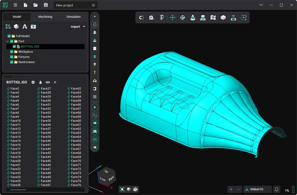
Some visualization control hotkeys can be changed in the System settings window on the Visualization tab.
Visualization parameters can be changed using the View Control toolbar on the left side of the main window or via the context menu of the graphic screen:

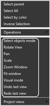
The first four elements switch the actions performed by the left mouse button:
- Select objects mode: Left-click will select objects from the screen (this is the default state).
- Rotate view: Moving the mouse while pressing the left button will rotate the view.
- Pan: Moving the mouse while pressing the left button will shift the view.
- Scale: Moving the mouse while pressing the left button will scale the view.
However, all these actions can be easily performed without changing the mode:
- To rotate the view, move the mouse with the right button pressed.
- To shift the view, move the mouse while pressing the middle button.
- Rotate the mouse wheel to zoom.
There are additional methods for changing the view using hotkeys. See the following topics: Window zoom, Interactive rotate, Interactive pan,Interactive zoom in-out, Zoom extents.
For quick scaling to display all visible objects, use the  button or the Fit window menu item.
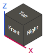
The view cube and standard views are described on the View cube page.
Use the Undo/ Redo menu items to quickly return to the previous or next view.
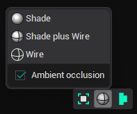
Display mode settings:
The  button with the drop-down menu allows you to switch the display mode of three-dimensional objects:
- Shade: shaded without edges
- Shade plus Wire: shaded with edges
- Wire: edges only
Clicking on the button itself toggles these modes alternately.
Ambient occlusion is a shading and rendering technique used to calculate how exposed each point in a scene is to ambient lighting. See the example below.
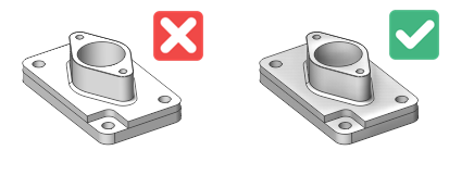
Ground plane. See View cube menu.
Equipment color schemes. Control the colors used to display the machine. Contrasting colors distinguish kinematic links, while static components remain neutral.
- Project Colors. Preserves the original model colors.
- Gunmetal. Applies an industrial color palette.
- Restrained. Applies an alternative industrial color palette.
Robot manipulators retain their native manufacturer colors in every scheme.
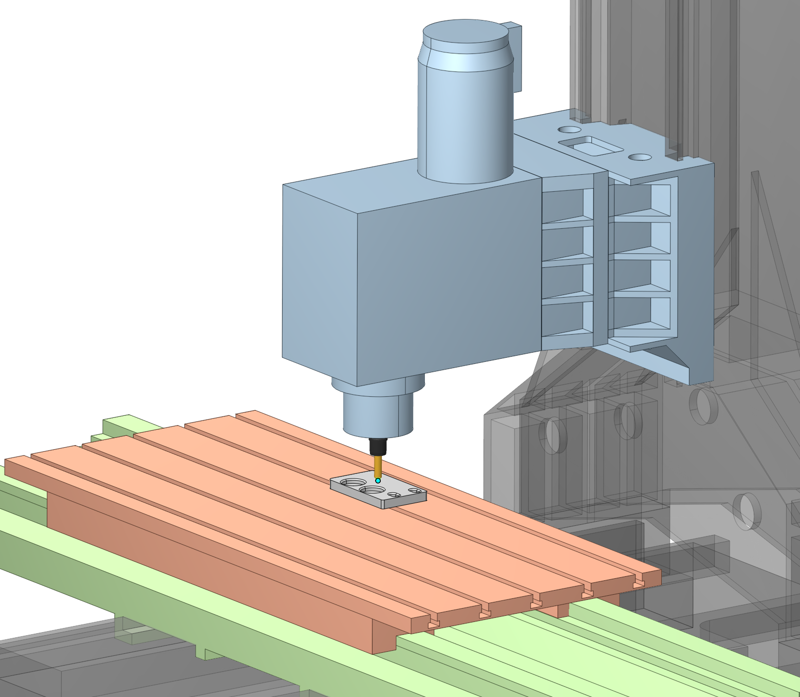
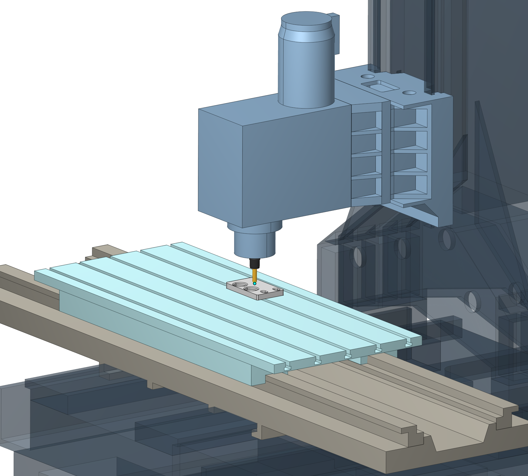
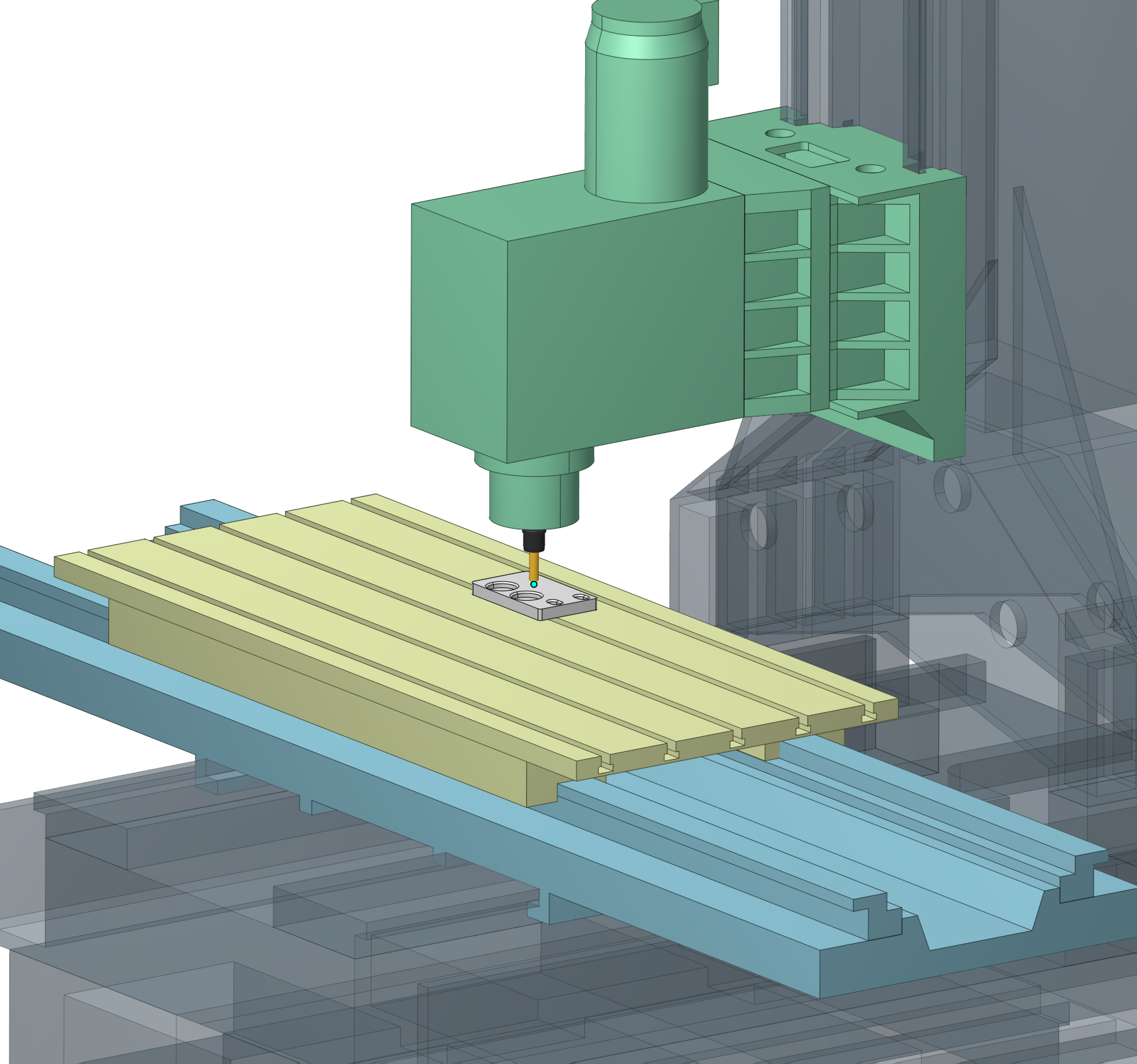
Examples of equipment color schemes in the 3D view.
Display settings for individual objects are available on the Visibility panel. Details
Turn mode:
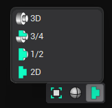
The  button above defines a visualization mode for revolution bodies only:
- 3D
- 3D without a quarter
- Half of 3D
- 2D axis section.
Interactive linear axis ruler:
The interactive linear axis ruler displays the current coordinate and travel limits when a machine node is dragged along a linear axis in the 3D view. Details