Blade Machining
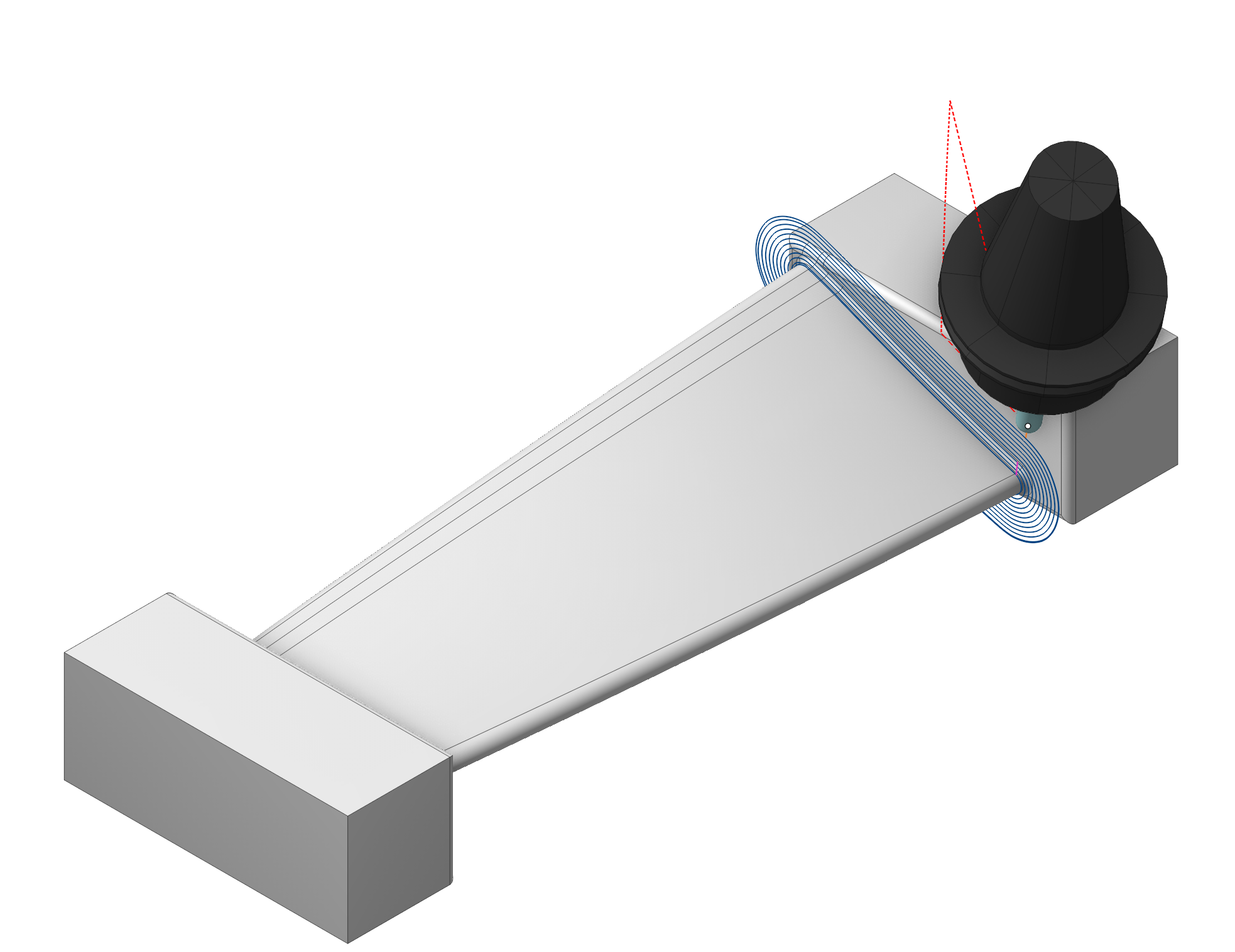
Application area:
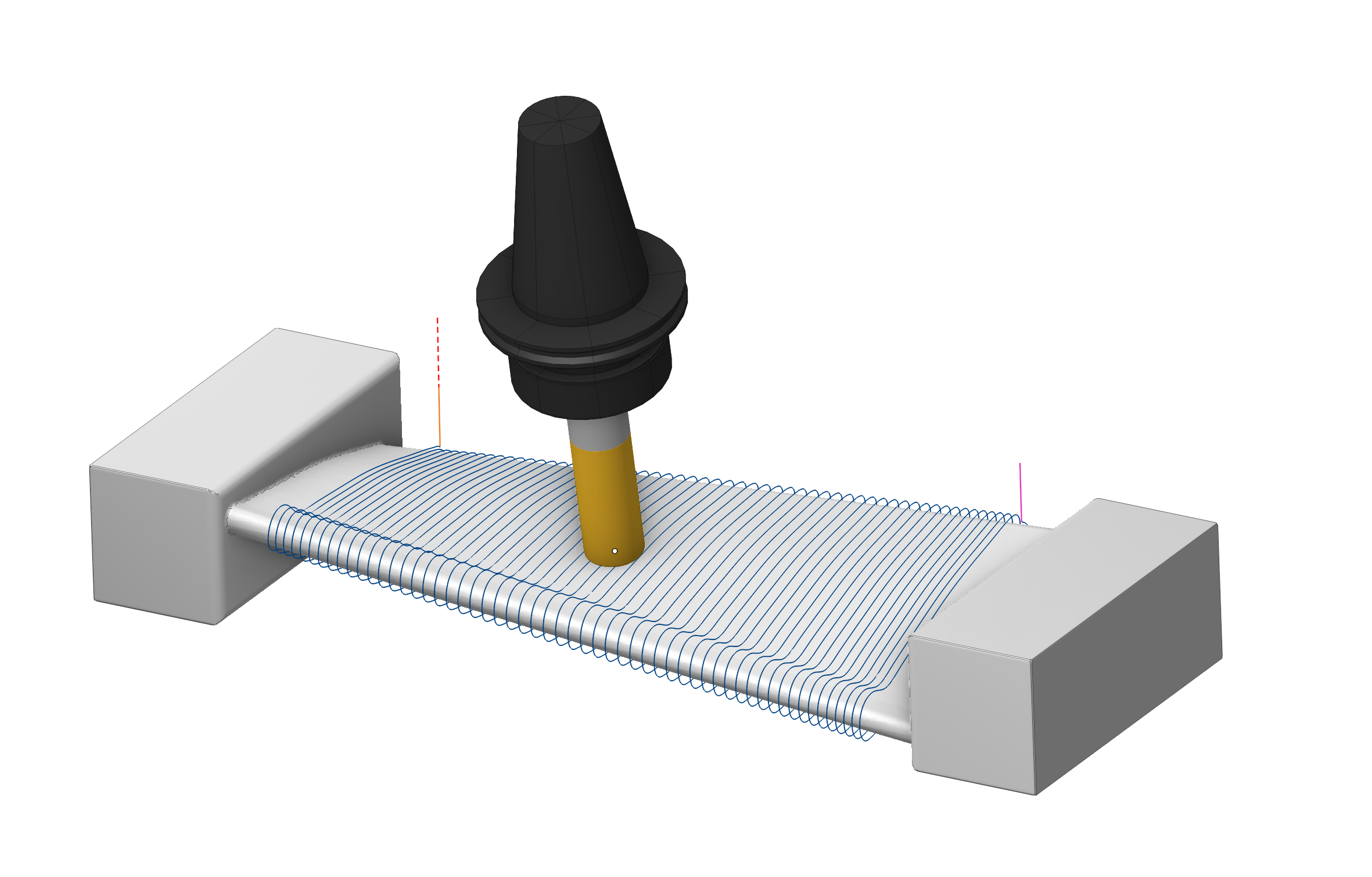
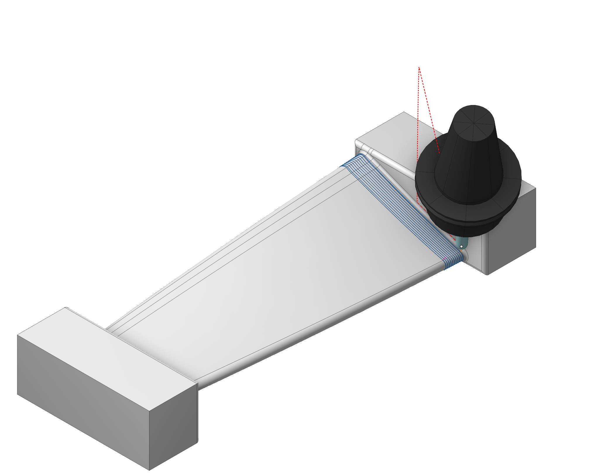
The Blade Milling operation is a specialized multi-axis finishing operation for machining single blades of compressors, turbines, and impellers. The operation machines the blade airfoil, the hub (platform) surfaces with fillets, the blade root zone, and the leading and trailing edges, using a rotary-axis machining model: toolpath passes are built around a user-defined rotary axis and projected onto the part surfaces.
What it is used for typical scenarios:
Finishing of the airfoil profile with a continuous Spiral pass, separate Circular loops, or longitudinal Linear passes between the edges.
Machining of the hub (flow-path) surfaces and fillets adjacent to the blade.
Additional cleanup passes in the root zone of the blade next to the hub.
Dedicated longitudinal machining of the leading and trailing edges with control of the tool contact point height.
Compensation of thin-blade deflection by a smoothly varying finishing stock (Bend compensation stock).
Setup:
The Setup tab is used to configure the primary parameters of the project. This can involve the positioning of the part on the equipment, the coordinate system of the part, and more. See more
Job assignment:
Blade surfaces. The set of faces forming the blade airfoil (pressure side, suction side, and edge surfaces). Required when the Target zone is Blade, Root zone of blade, or Edges.
Hub surfaces. The set of faces forming the hub (platform, flow path) together with the fillets between the hub and the blade. Required when the Target zone is Hub. For the Root zone of blade the hub surfaces act as the limiting geometry of the machined area; they may be omitted — the calculation then runs without the hub limitation.
Properties. Displays the properties of an element. It is possible to add the stock. You can also call this menu by double clicking on an item in the list.
Delete. Removes an item from the list.
Restrictions. It allows you to restrict areas that should not be machined. See more
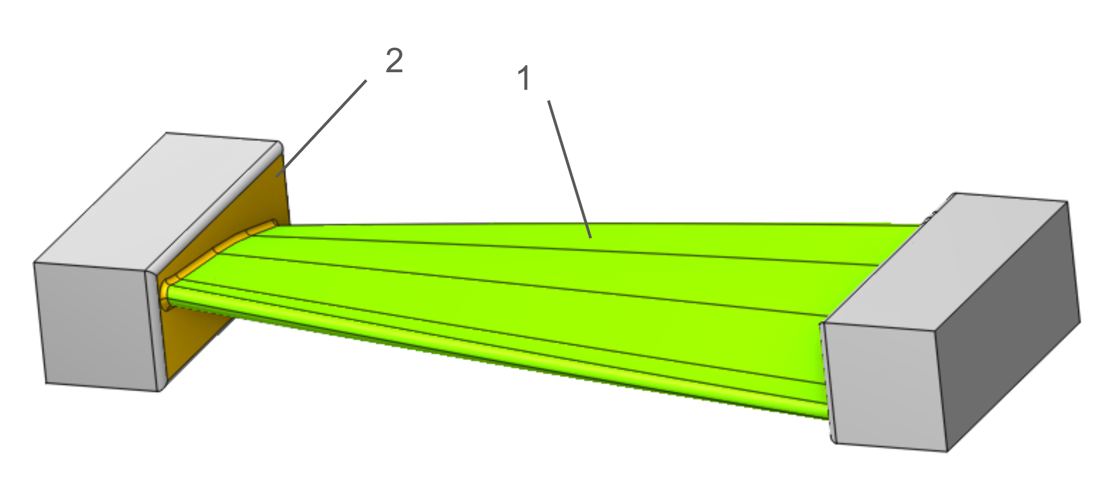
1-Blade Surfaces, 2-Hub Surfaces
Strategy.
Target zone.
The Target zone parameter selects which structural element of the blade is machined. It is the main switch of the operation: it defines the machining strategy, the required geometry groups, and the set of visible parameters.
Blade. Machining of the airfoil profile. Passes are generated around the rotary axis over the whole working range of the blade and projected onto the Blade surfaces. All three trajectory forms are available (Spiral, Circular, Linear).
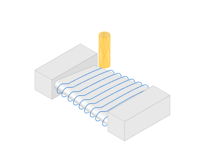
Root zone of blade. Additional passes over the lower part of the blade surfaces adjacent to the hub. The machined band is limited by the Zone height value measured from the hub. The zone is intended for cleanup with a different (usually smaller or tapered) tool after the main airfoil machining.
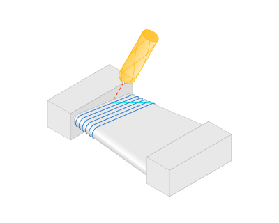
Hub. Machining of the hub surfaces and fillets: equidistant offset passes are built successively from the contour at the blade outwards with the constant Step over the Hub surfaces. The working band along the blade axis is set by the Zone height parameter. Outside the outer hub contour the passes are extended automatically; on the extension the next-pass feed is applied.
Edges. Dedicated machining of the leading edge (LE) and the trailing edge (TE) by longitudinal passes. The edges are detected automatically as curvature peaks of the airfoil cross-sections; the passes run along each edge and are distributed across the edge according to the Pass count and Arc length parameters. The height of the tool contact point can be controlled along the pass - Tool contact point.
Job zone.
It enables additional modification of the working area initially selected on the
Job assignment
tab.
Rotary axis. The system directs tool's axis vector from the designated Rotary Axis. The rotary axis position can be defined in the properties inspector. You can adjust the rotary axis interactively using the arrow or select it from the drop-down menu.
If the mode is set to the Along X, Along Y or Along Z, then the axis of rotation will be oriented along the corresponding axis of the coordinate system.
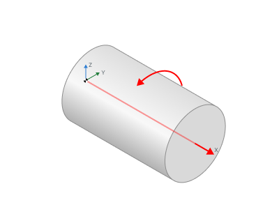
Direction. If mode is Custom(WCS) then axis vector must be defined manually in the fields X,Y,Z of custom direction group. Specify the direction cosines relative to each axis.
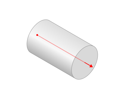
Origin. The Origin field defines the point that acts as the coordinate start for the chosen rotary axis .
Base CS. The Base Coordinate System (Base CS) changes the coordinate system between the global and local coordinate systems of the part.
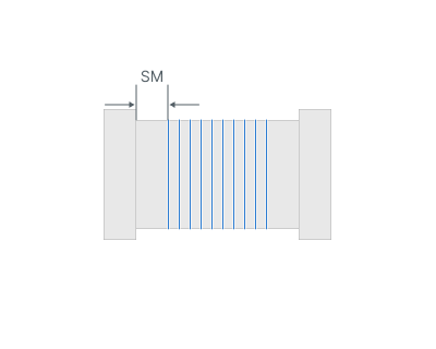
Start margin. The offset of the machining start from the blade root.
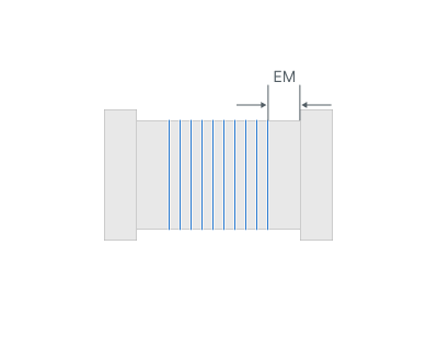
End margin. The offset of the machining end from the blade tip.
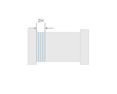
Zone height. For the Root zone of blade and Hub target zones: the height of the machined band measured from the hub along the blade axis.
Trajectory form.
The trajectory output format.
The trajectory can be in one of the following forms:
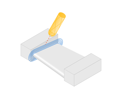
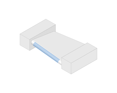
Linear. When you select this option, the work passes form as intersection lines between the machined surfaces and planes through the Rotary Axis. .
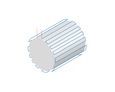
Circular. When you select this option, the work passes form as intersection lines between the machined surfaces and planes perpendicular to the Rotary Axis.
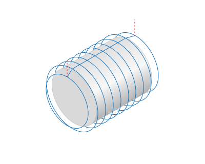
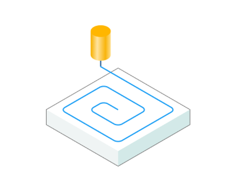
Spiral. Activating this option shapes the toolpath into a continuous helical line . The pattern is well suited for machining parts like screws and impellers.
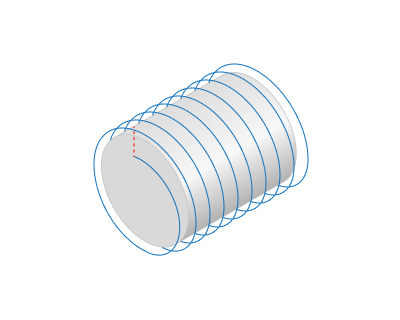
Step. It is the distance between tool passes along the rotary axis.
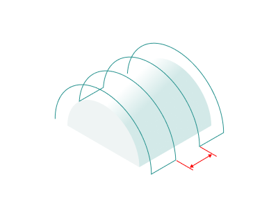
Axial direction. Depending on the feature of the Trajectory Form parameter, it either defines the direction of the tool passes themselves or the sequence of several tool passes. In the case of a spiral whose step matches the machining Step, this parameter influences the direction of the spiral's twist .
Forward. The tool passes is ordered in the Rotary Axis vector direction.
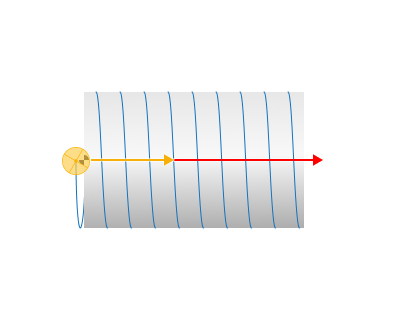
Backward. The tool passes are ordered in the reverse direction of the Rotary Axis vector.
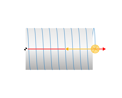
Side. For Linear and Circular modes in the Blade zone: selects which side of the airfoil is machined. In Circular mode with a single side selected the loops become open arcs limited by the edge margins.
Both. The tool can perform processing from both sides of the surface.
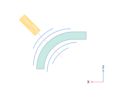
Convex (suction side). The tool can only process from the side with the positive direction of the surface normal vector.
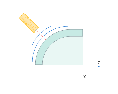
Concave (pressure side). The tool can only perform processing from the side opposite to the surface normal vector.
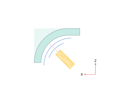
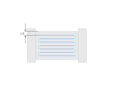
LE margin. Offset from the leading‑edge peak along the airfoil arc; default equals tool diameter.
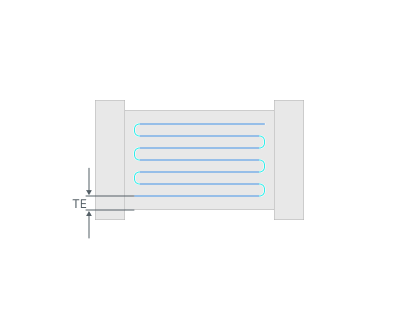
TE margin. Offset from the trailing‑edge peak along the airfoil arc.
Tool contact point.
Сhange the tool's contact point.
One point. A fixed contact point held constant along the whole pass. Tool Contact Point (TCP) is a specific location on a cutting tool that defines the primary interaction point between the tool and the workpiece surface or geometric entities during machining operations. This group works similarly 5D Surfacing operation - Tool contact point. See more
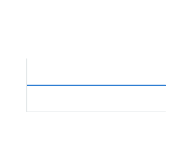
Changing the tool contact point along the pass
Two point. С hange the tool's contact point from the initial line to the final line. This group works similarly 5D Surfacing operation - Contact Points. See more
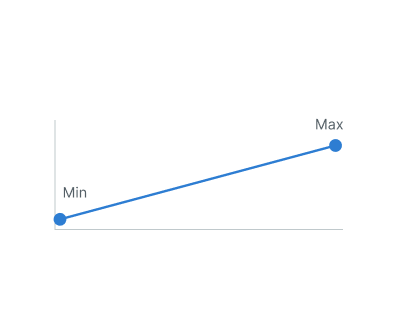
Changing the tool contact point along the pass
Wave. The contact point oscillates sinusoidally between the Start point and End point values with the specified Wave period (the wavelength measured along the pass, default — 20 linear units).
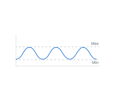
Changing the tool contact point along the pass
Wave period. Wave distribution gives the most uniform wear of the tool corner radius.
Note.
The lead angle in every point of the pass is computed from the current contact height h and the tool corner radius r as:
lead = arccos(1 - h/r)
The Lead angle field of the Tool orientation group is hidden while the block is active.

Tool orientation.
The Tool orientation group controls the direction of the tool axis relative to the machined surface.
Edge normal smoothing.
The Edge normal smoothing block smooths the contact normal of the tool in the approach zone near the leading and trailing edges. On thin edges the surface curvature changes abruptly, which causes a sharp "dive" of the tool axis when the pass crosses the edge; the smoothing blends the normal over a distance before the edge and removes the jerk of the rotary axes.
Bend compensation stock.
The Bend compensation stock block adds a smoothly varying stock along the blade to compensate the elastic deflection of a thin blade. Under the cutting force the free end of the blade bends away from the tool, so a uniform finishing pass leaves an uncut layer near the tip. The block leaves an intentional, smoothly growing stock in the flexible region; this stock is removed by a final light pass with small cutting forces. The maximum additional stock at the peak position, in linear units (default — 0.05).
Milling type.
Сan be assigned in almost all operations, except for the curve machining operations. This allows the user to control the required milling type (climb or conventional) during the toolpath calculation process. This parameter group works similarly to the Waterline roughing operation. See more
Sorting.
Controls the sequence of toolpath passes during the surface machining .
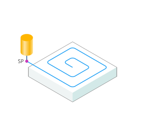
Start Point. The point defining the beginning of the plunge.
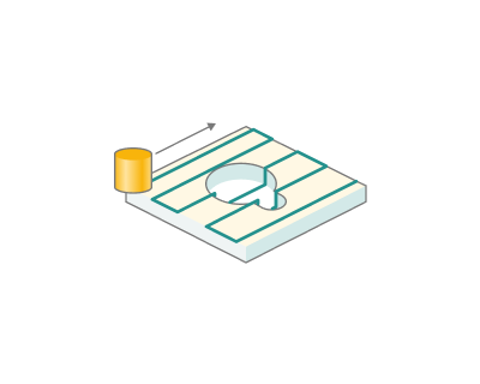
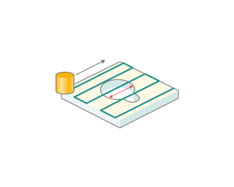
Hole capping. Quite often a geometrical model has holes the machining of which has been performed earlier or are required to be machined in a later operation. In this case, when machining the surface that has the hole, it can be ignored. The ignored holes can be of any shape (not always round). The defined size describes the diameter of a disk that can cover the hole.