ENCY 3 User Manual
  • ENCY 3 User Manual
v3.1.20
Search Results for

    Show / Hide Table of Contents
    • Introduction to ENCY
      • System requirements
      • Configurations and options
      • Standard package
      • Program installation and launch
      • System files
      • Technical support
    • Brief and to the point
      • Ideology of ENCY
      • Fast familiarization with the system
      • What's new in ENCY 3.0
    • General information
      • Home Page
        • Project library
      • System's main window
        • Application Toolbar
          • Smart Snap
          • Measurement and analysis
          • Autosaves and Project snapshots
          • Project library
          • Machine setup (project template)
          • AI assistant
          • Version info window
        • Graphic window and visualization control
          • Standard views
          • Objects selection mode
          • Window zoom
          • Interactive rotate
          • Interactive pan
          • Interactive zoom in and out
          • Zoom extents
          • Undo view
          • Redo view
          • Section plane
          • Rotation Mode
          • Gimbals
          • Interactive linear axis ruler
        • Work modes
        • Selection filter
        • Visibility panel
        • Geometrical coordinate systems
          • Creation of the coordinate system via dialogue window
          • Smart LCS creation
          • Creation of the coordinate system by the origin point and two leading vectors
          • Creation of the coordinate system by the current view direction
          • Changing properties of an existing coordinate system
        • Machine axes control panel
          • Interactive Machine
        • Graph of the machine axes window
        • Holder occlusion check utility
        • Utilities button of main panel
        • Help button of main panel
        • Process indicator
        • Application events notifications
        • Multiproject interface
      • System settings window
        • Folders tab
        • Measurement units tab
        • Visualization tab
        • Colors tab
        • Import tab
        • Additional tab
        • Machining tab
        • Online features tab
        • Extensions tab
        • PLM connections tab
      • Exchange files
        • Projects files
        • Importable files
        • DXF export
        • Postprocessor tuning files
        • NC program files
        • Interpreter files
        • Machine schema files
        • Encrypted containers .stfc
        • Machine setup files
      • Updating
      • Container manager
      • Licence manager
      • System logs
      • Work with a team in the cloud
    • Geometrical model preparation
      • Geometrical model structure
        • Geometrical objects types
          • Faces, meshes, curves and points
          • Groups (folders)
          • Active folder
          • PMI
        • Geometrical model structure window
        • Object selection
        • Intellectual object selection
        • Geometrical model structure editing
          • Creating a new group
          • Geometrical model structure updating
          • Working with the exchange buffer
      • Geometrical objects import
        • Importing objects from IGES files
          • Requirements for IGES-file
          • Types of importable objects
          • Recommendations on how to adjust IGES-export module in your modeling program
        • Importing objects from STEP files
        • Importing objects from DXF files
        • Importing objects from PostScript files
          • Installing the GhostScript Library
        • Importing objects from STL files
        • Importing objects from PLY files
        • Importing objects from AMF files
        • Importing objects from VRML files
        • Importing objects from 3dm files (Rhinoceros™)
        • Importing objects from Parasolid™ files
        • Importing objects from SolidWorks™ files
        • Importing objects from SolidEdge™ files
        • Importing objects from SGM files
        • Importing objects with CAM system addins
        • Importing objects from 5DC files
        • Addins for CAM system
          • Addin Manager
          • Addin's list
            • Autodesk Inventor™ toolbar & import addin
            • CADbro™ toolbar
            • FreeCAD™ toolbar & import addin
            • Alibre Design™ toolbar & import addin
            • IronCAD™ toolbar
            • NX™ toolbar & import addin
            • Rhinoceros toolbar & import addin
            • SolidEdge™ toolbar & import addin
            • SOLIDWORKS™ toolbar & import addin
            • SpaceClaim™ toolbar & import addin
            • ZW3D™ toolbar & import addin
            • Onshape™ connector
            • CAXA 3D™ toolbar
            • KeyCreator™ toolbar
            • SolidCAM™ toolbar & import addin
          • Associativity for Addin`s
      • Editing geometrical model
        • Geometrical object properties
          • General tab
          • Visual tab
          • Machining tab
          • Parameters tab
        • Changing visual properties
        • Delete
        • Spatial transformations
        • Inversion
        • Surfaces boundary projection
        • Join curves
        • Surface triangulation
        • Creating text
        • Intersect
        • Sew Faces
        • Export of 3D Model
        • Patch hole
        • Extract isolines
        • Simplifying geometrical model
        • Working with splines
        • Extend surface
      • 2D Geometry sketcher
        • Building and editing elements
        • Line
        • Arc
          • Two points and radius
          • Center, starting point and angle
          • By three tangents
          • Edit arc
        • Circle
          • Build Circle with Center and radius. Edit circle
          • Circle by three tangents
        • Rectangle
          • By two points
          • By side and height
          • By center and point
          • Edit rectangle
        • Contour
          • Build by elements
          • By zone or border
          • Edit contour
          • Spline
          • Archimedean spiral
          • Function profile
        • Chamfer and Rounding
        • Dimension
          • Linear dimension
          • Radial dimension
          • Angular dimension
        • Offset
        • Annotations
        • Trim function
        • Split object
        • Additional functions
          • Copy
          • Shift
          • Rotate
          • Mirror
        • Named block
          • Block parameterization
        • Constraints
          • Editing links in a block
        • Drawing example
        • Example of building a drawing using constrains
        • Planes
      • Design (3D Geometry)
        • Main window
        • Design in 2D mode
        • Design in 3D mode
        • Direct Modeling
      • Nesting
    • Creating machining technology
      • Common principles of technology creation
        • Selection of a machine and its parameters definition
        • Defining machining sequence
        • Creating new operation
        • Executing operation
        • Generating NC code
        • Machining report
        • Standard machining sequences
        • Operations setup
          • Geometrical parameters of an operation
          • Defining part, workpiece and fixtures
          • User operations
          • Operation status panel
          • Conversion of arbitrary toolpath to 6D Contour operation
        • Tool path template
          • Macro commands in the tool path template
        • Auxiliary operation
        • Collision Detection in Background Simulation
          • List of Operation Statuses
        • Editing of the Collisions Ignore List
        • Toolpath recalculation control
        • User defaults in inspector
      • Structure of the machining mode
        • Machine setup panel
          • 3D Tool Compensation
        • Setup panel
          • Positioning of part at machine (Workpiece setup)
          • Workpiece coordinate system (G54 - G59)
          • Operation local coordinate system
          • Tool orientation
        • Job assignment
          • Base surface
          • Faces
          • Curve
          • Job zones
          • Top and bottom levels
          • Pocket feature
          • Restrict zones
          • Tabs
          • Job assignment for engraving and pocketing operations
          • Job assignment for hole machining operation
            • Defining holes by coordinates
            • Defining holes by using a geometrical point object
            • Automatic hole recognition
            • Creating hole pattern
            • Holes sorting
          • Recognize features
          • Restrictions
        • Operation parameters
          • Check Holder (Avoid collisions)
          • Layer time
          • Power
          • Use new calculation method for Rotary roughing/finishing
          • Weaving
        • Links/Leads
          • Approach/Return
            • Approach and return rules
              • Approach/return rules edit window
              • Machine's approach/return list
            • Tool change position
          • Safe Motions
          • Advanced Links Settings
          • Links
            • Links based on the Roughing waterline
            • Links for 3D/5D advanced operations
            • Links for 3D operations
            • Links for countouring operations
            • Links in сladding operations
            • Links in drilling operations
          • Leads
            • Leads based on the Roughing waterline
            • Leads based on the Face Milling
            • Leads for 3D operations
            • Leads for 3D/5D advanced operations
            • Leads for countouring operations
            • Leads for сladding operations
          • Distances
            • Distance for 3D operations
            • Distances based on the Face Milling
            • Distances based on the Roughing waterline
            • Distances for 3D/5D advanced operations
            • Distances in drilling operations
          • Allow plunges
        • Transformation
          • Cylindrical interpolation
          • Polar interpolation
        • Feeds/Speeds
          • Corner control
          • Feeds/Speeds (Calculate)
        • Holes (Drill points)
        • Fixtures
      • Structure group of operations
        • Setup stage
        • Part (group)
        • Copy of part
        • Multiply Group
      • Sequencing mode
      • List of types of machining operations
      • Basic technology terms
        • Group
        • Part
        • Workpiece
        • Machining result
        • Tool
          • Mill tool
          • Lathe tool
          • Tool overhang
        • Stock
        • Relief Angle
        • Lateral Angle
        • Adaptive Step (Selection step by scallop height)
        • Frontal angle
        • Machining methods in drive operations
        • Trohoidal machining (Equidistant legacy)
        • Tool magazine
        • Tool compensation in mill operations
      • Mill machining
        • Types of machining operations
        • Holes
          • Hole machining
          • FBM Mill
            • FBM Machining Procedure
            • FBM Procedure Library UI
            • Feature Tree UI
            • Assigning procedures to features UI
            • Procedure Editing UI
            • Operations generation parameters
            • FBM Mill operation parameters
        • 2D
          • Pocketing
          • Engraving
          • 2D contouring
        • Basic
          • Face milling
          • Roughing waterline
            • Plunge roughing
          • Finishing waterline
          • Roughing plane
          • 2.5D contouring
          • Flat land
          • 3D contouring
        • Advanced
          • Combo finish
          • Surfacing
          • Scallop
          • Helical
          • Morph
          • Undercut waterline
          • Swarf
          • 5D Roughing waterline
          • 5D by meshes
          • 6D Contouring
            • Parameters of Drive Faces
            • Parameters of Curves
            • 5-axis milling of the ruled surfaces by the flank of the mill
            • Feeds control feature
            • Using custom vectors feature
          • Contour polishing
        • Rotary
          • Rotary waterline
          • Rotary roughing
          • Rotary finishing
          • Morph 4D
          • 4D Surfacing
          • 4D Contouring
        • Turbomachinery Milling
          • Impeller Machining
          • Blade Machining
        • Rest machining
          • Corners cleanup
          • Pencil
          • Chamfering
        • High performance cutting (HPC)
        • Operations setup
          • Using design and machining features in Job Assignment
            • Creating operations for selected features
            • Spline curves drawing
          • Job assignment for the 2.5D machining operations
          • Milling by axis count
            • Operations for 2/2.5-axes milling
              • 2.5D machining operations
            • Operations for the 3-axes milling
            • Operations for 4-axes and 5-axes milling
              • 4-axis milling with engraving and pocketing operations
              • 5 axis machining
              • Indexed 5-axes milling
              • Rotary machining using cylindrical interpolation
              • 5 axis tool path conversion
              • Axes map for 5-axis machines
        • Adaptive
        • Pocketing strategies
      • Lathe machining
        • Types of lathe machining operations
        • Lathe machining operations
          • Lathe facing
          • OD Roughing and ID Roughing
          • OD Finishing and ID Finishing
          • OD Grooving, ID Grooving and Face grooving
          • OD Threading and ID Threading
          • Profile Threading
          • Lathe part-off
          • Lathe hole machining
          • OD Adaptive turning
          • Part-off with takeover
        • Lathe cycles
          • Profile cycle
          • Offset Roughing
          • Offset cycle (ISO G73)
          • Roughing
          • Roughing cycle
          • Facing
          • Grooving cycle
          • Slotting cycle
          • Thread cycles
            • Standard form thread
            • Threading cycle types
          • Zigzag cycle
          • 4-axis turning
          • Parting-off cycle
          • Peck groving/drillling cycle
        • Operations setup
          • Job assignment of the lathe operations
            • Job assignment element parameters
            • Contour editing modes
          • Cutting conditions of lathe operations
          • Job assignment for hole machining operation
            • Defining holes by coordinates
            • Defining holes by using a geometrical point object
            • Automatic hole recognition
            • Creating hole pattern
      • Mill-turn Machining
        • Lathe-milling machines types
        • Setting-up tooling
        • Positioning of part
        • Tool change position
        • Positioning of tool
        • Obligatory testings before the final generation
        • Counter spindle machining
        • U-axis turning
      • Machining on cutting machines
        • Jet cutting
        • 4D Jet cutting
        • Jet cutting 5D
        • Operations setup
          • Jet cutting job assignment
          • Job assignment of EDM and Jet cutting 4D operations
            • 2D job assignment item properties
            • 4D job assignment item properties
            • Synchronization lines
            • Approaches/returns
            • Bridges
            • Multiselect feature
            • Wire EDM feature
          • Machining conditions of EDM and Jet cutting 4D operations
          • Strategy of EDM and Jet cutting 4D operations
      • Knife cutting
        • Cutting tool - "knife"
        • 2D knife cutting
        • 6D Knife cutting
        • Knife corner retraction
      • Wire EDM machining
        • Wire EDM machining operations
          • Wire EDM 2d Contouring
          • Wire EDM 4d Contouring
          • Wire EDM coreless pocketing
            • Pocketing parameters
            • Wire thread points
        • Operations setup
          • Job assignment of EDM and Jet cutting 4D operations
            • 2D job assignment item properties
            • 4D job assignment item properties
            • Approaches/returns
            • Bridges
            • Multiselect feature
            • Synchronization lines
            • Wire EDM feature
          • Machining conditions of EDM and Jet cutting 4D operations
          • Strategy of EDM and Jet cutting 4D operations
      • Machining on industrial robots
        • Setting the coordinate system of the tool and the workpiece
        • Programming the robot's 6th axis
        • Programming the rails position
        • Programming the rotary table
        • Robot axes map
        • Programming robot's transitions (obsolete method)
          • The planning of the links
      • Multi Task Machining
        • Submachine definition in the machine schemas
        • Swiss lathes programming
        • Automatic insertion of wait labels
      • Move part operations
        • Machine requirements for part moving operations
        • Clamp devices control
        • Pick-and-place
          • Point Pick-and-Place
        • Turn take over
          • Phase synchronization in Turn take over
        • Sub spindle working
        • Bar feeding
      • Welding
        • Point welding
        • Welding 5D and Welding 6D
      • Additive manufacturing
        • Area cladding
        • Curve cladding
        • Cladding 3D
        • Cladding 5D operation
        • Planar slicing
        • Non-planar slicing
        • Direct cladding
      • Disc tool machining
        • Disc tool
        • Disc cutting 2D
        • Disc cutting 6D
        • Disc roughing
      • Probing
        • Creating own probing cycles (templates)
        • Types of measuring cycles
        • Use of prepared measuring cycles
        • Probing templates window
      • Spray painting
      • Legacy operations
        • 2.5D chamfer machining operation
        • 2.5D cover machining operation
        • 2.5D pocketing operation
        • 2.5D wall machining operation
        • Combined operation (waterline-drive)
        • Drive finishing operation
        • Drive roughing operation
        • Saw operation
        • Finishing plane
        • Optimized plane
        • Complex
    • Simulation
      • Tool path motion
        • The structure of the tool path
        • The list of the basic CL-data commands
        • The selection of the CL-data commands from the graphical view
        • Tool path editing
        • Tool path spatial transformations
      • Controlling simulation process
        • Tool motion controlling
        • Tool path errors detected by simulation
        • Feed rates optimization
        • Assigning workpiece parameters
        • Turbo simulation mode
        • Export simulation result as model
        • Delete chips function
      • Simulation of machining by NC program
        • G-code based program simulation
        • Creating your own interpreter
      • Painting simulation
      • Solid Simulation
    • Machining tool features
      • Tools window
        • Manage libraries
        • Milling tool editing
        • Turn tool editing
        • Mill holder selection window
      • Project tool list
      • Creating shaped tools
      • Holders (*.osd) window
      • Machining tools import API
      • Tool assemblies
        • Adapting a machine for advanced tools mode.
        • Component libraries
        • Building a tool assembly
    • Extension and integration possibilities
      • Scripts in ENCY
        • Brief Scripts in ENCY
        • Scripts IDE
        • Application Programming Interface
        • Scripted operation
        • Operation with scripted events
        • Scripted ENCY launch
      • PLMIntegrations
        • Authorizing an External System in the CAM Main Window
        • Importing a Geometry Model from an External System
        • Installing and Configuring PLM Integration Modules
        • Loading and Saving Machines to an External System
        • Loading and Saving Postprocessors to an External System
        • Loading and Saving Tools to an External System
        • Opening and Saving Projects to an External System
      • Extensions of the CAM system
        • Installing extensions from a file
        • Installing extensions using the command line
      • Macro
        • Recording a macro
        • Editing steps
        • Saving a macro
        • Running a macro
        • Editing the code
      • Extension Store
    • Program's licensed modules
      • Adaptive
      • Robot +
      • Robot Mill
      • Advanced multi axis control
      • Operations
        • Sawing
        • 5D cutting
        • Welding
        • Cladding
        • Knife
        • G-code based, G-code based lathe
          • Job assignment for G-code based operation, G-code based lathe operation
            • Keyboard shortcuts for working with NC text
          • Rapid feed
      • Operations which requires adaptation
        • Heat Treatment
        • Welding
        • Cladding
        • Jet Cutting
      • Teamcenter Integration Module
    • Appendix
      • Operations matrix
      • CAM system features matrix
      • List of interpreters
      • Getting trial license
      • Bug report best practice
      • Troubleshooting with authorization in the license manager
      • Additional software and installation changes

    Strategy of EDM and Jet cutting 4D operations

    Alteration of the many available parameters for the machining strategy are made in the Parameters –> Strategy window. This window is accessed by clicking the Parameters button which is located in the Machining mode. On the Strategy tab there are many panels with input fields and explanatory images. The composition of these panels are determined by the type of current operation.

    Wire EDM machining operation of contours includes the following set of parameters:

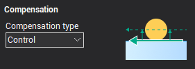
    • Compensation type – determines the way in which the offset of the wire is performed on a given contour.
    images/download/attachments/157865970/image2024-8-1_18-41-48.png

    The following compensation types are available:

    • Computer – the system itself calculates the corrected wire toolpath and the codes to enable compensation are not output in the G-code. In the registers responsible for compensation, the values of the offset are not added.
    • Control – the system outputs into the G-code the codes to enable compensation, and does not offset the wire. The registers responsible for the value of compensation, record the values of the offset for each pass. Compensation is calculated by the CNC control.
    • Both – the system outputs into the G-code the toolpath with provision for offsets already, but into G-code are outputted codes enable of compensation also. Registers that are responsible for the value of the compensation aren't filled.
    • Reverse Both – correction is calculated similarly in the Both regime, but the direction of the compensation changes to the opposite.
    • Off – wire offset values entered for the contour are not produced. Codes for compensation into the G-code are not output. Registers that are responsible for the amount of the compensation system are not used.

    The value of compensation for each pass is defined as an Offset value, in the Feeds/Speeds tab, plus the stock value of the operation. For the compensation types Computer, Both and Reverse Both the value is used to construct an equidistant path, and for the Control type the value is entered into the register with a number equal to the Offset code, specified for the corresponding pass in the Feeds/Speeds tab.

    The direction of compensation can be set for each contour individually within the Job assignment of an operation.

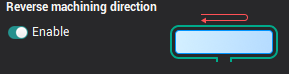
    • Reverse machining direction – if you enable this option, the system will choose the direction for the pass, which provides the smallest length of the toolpath. If the option is disabled, then the direction of the pass will always correspond to that specified in the Job assignment for the contour.
    images/download/thumbnails/157865970/image2024-8-1_18-42-18.png

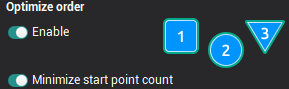
    • Optimize order – this strategy determines the order of contours passes when the job assignment has more than one contour. The length of transitions between the contours will be minimal if the Optimize order option is enabled. If this option is disabled, then the order of the passes would be consistent with the order of the contours in the Job assignment.
    images/download/thumbnails/157865970/image2024-8-1_18-42-39.png

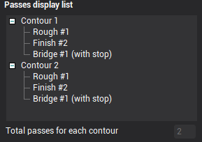
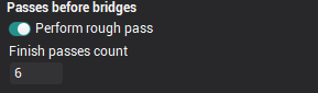
    • Passes before bridges this panel determine the number of passes that will be performed for each contour of the job assignment, to trim bridges. If the formation of the bridges is disabled, then these parameters determine the total number of passes for each contour. If the option Perform rough pass is included, then one rough pass for each contour will be executed, as well as the number of passes as defined in the Finish pass count field. When you turn this option off, rough and finish cuts to trim the bridges are not made. Approximate sequence of passes, depending on the set parameters displayed on Passes display list.
    images/download/attachments/157865970/image2024-8-1_18-43-5.png

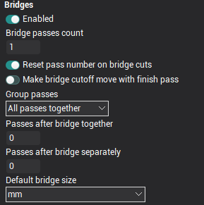
    • Bridges. In some cases, for example, if the job assignment is a series of closed contours, passage of the full contour details may lead to an undesirable deposition of parts of the workpiece. The system provides a set of parameters that allow to keep the special sections without machining on the workpiece, these are called bridges. When the wire approaches such zones, the system can be add a Stop command position, to allow additional steps to fix certain parts of the workpiece, then the bridges can be automatically trimmed. Location of the bridges can be specified for each contour individually in the Job assignment section. In the Bridges section it is possible to configure the number of passes for cutting bridges, the number of passes for cleaning the contour after clipping of the bridges, and the parameters determining the sequence of these passes. If the Enabled is not selected then no bridges are cut and no clean cut after cutting bridges is available, accordingly, all fields on the panel are unavailable.
    images/download/attachments/157865970/image2024-8-1_18-44-31.png

    The Bridge pass count field sets the number of passes which will be performed for each bridge cutting on each contour. W hen the option Reset pass number on bridge cuts is enabled, then the count rates for the passes that define the cutting conditions for the bridge cutting moves are reset to the start value, ie from the value that is set on the Feeds/Speeds tab in the Start pass # field, otherwise, the count rates of the bridge cut passes will continue. For example: if the last contour pass prior to the bridge cutting was #2, the first bridge cutting pass would be #3 and the next #4 etc.

    If the option Make bridge сutoff move with finish pass is enabled, then the bridge(s) will be cut on the final pass followed by the lead out move, then, if the bridge pass count is greater than one, the subsequent bridge cuts will be performed. If Make bridge сutoff move with finish pass is disabled, on the last contour pass, the lead out move will be performed leaving the bridge, and then the bridge cutting move will be preformed.

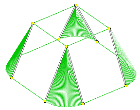
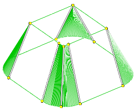
    The fields Passes after bridge together and Passes after bridge separately together determine the number of finishing passes after bridge trimming that will be performed along the length of each contour as a 'clean up' pass. The difference between these two options is only affected if there is more than 1 contour feature. Example sequences for both types of final passes are shown in the pictures below:

    The sequence of execution of "together" passages: The sequence of execution of "separate" passes:
    images/download/attachments/157865970/image2024-8-1_18-46-51.png images/download/attachments/157865970/image2024-8-1_18-53-15.png

    In the drop-down Group passes menu You can choose the way of grouping different types of passes for when working with several contours.The following options are available:

    • All passes together – all roughing passes, bridge cutting passes and finish passes are performed for each contour, only when completed is the next contour started.
    • Bridges and finish together – all rough passes for all contours are performed, then all bridge cutting and finish passes are performed together for each contour.
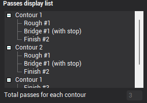
    • Rough, bridges and finish separately – first, all contours rough passes are run without bridge cutting, then the bridge cutting is performed for all contours without finishing, and finally, the finish cuts for all contours are performed.

    The approximate sequence of the passes, depending on the selected parameters, are displayed in the Passes display list.

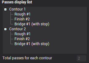
    • Passes display list. On the Strategy tab for the Wire EDM operation there are many available options for contour machining that control the manner and the order of processing for the contours of the job assignment. To better understand the impact of a particular parameter on the machining sequence, there is an information panel available called Passes display list. When you change a value or parameter which influences the strategy process, this also changes the contents of this information panel. The main area of the panel takes the form of two-level tree type display. In this tree, the top-level displays the contours, and the lower level displays the types of and number of passes that defines the cutting conditions. In the bottom of the panel is a box that display the total number of passes which are made for each contour using the current settings.
    images/download/attachments/157865970/image2024-8-1_18-54-28.png

    Note: The information panel Passes display list only displays information and all of the fields are read-only. Alteration of the information displayed can only be made using the parameter options that are available in the main window. The information shown in the panel is approximate and may not correspond to the exact sequence of machining since its formation does not take into account the actual geometry of the contours that are in the job assignment of operations. By default, the list always contains two abstract contours.

    Note: When specifying the number of passes in the strategy, these should be closely monitored so that the number of passes in the field Total passes for each contour coincides with the number of passes defined for the cutting conditions on the Feeds/Speedstab. If there is a discrepancy in the number of passes, then the machined contours may have material remaining upon completion.

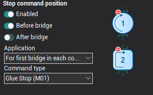
    • Stop command position. The options located on this panel allow control over the output of the stop commands in the G-code for the bridge cutting passes. The stop commands are only output into the G-code when the Enabled option is selected. The next two parameters define the time of output for the stop command. The Before bridges option enables the stop command which will be output after the bridge approach move, prior to its cutting. The After bridge option enables the stop command which will be output after the cutting of the bridge but before the lead out move from the endpoint to the wire cut point. These parameters operate independently, ie they can be set simultaneously.
    images/download/attachments/157865970/image2024-8-1_18-54-59.png

    The drop-down list Application determines how the bridges should use the technological stops. The options include:

    • For every bridge – stop command will be output for the bridge cutting move for every bridge specified in the operation.
    • For first bridge in each contour – stop command will be output only for the first bridge of each contour.
    • For first bridge in operation – stop command output only when cutting the first bridge of the operation.

    Command type this parameter defines a specific type of output stop command, and can take one of two values:

    • Glue stop (M01) – the "optional" or "additional" stop allows, in contrast to the usual stop command (M00), when the switch on the CNC control panel is selected, it allows the operator to decide whether the process should stop. Typically, this command corresponds to the auxiliary code M01.

    • Stop (M00) – this command causes an unconditional interruption of the G-code execution. Usually, it corresponds to the auxiliary code M00.

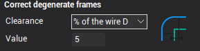
    • Correct degenerate frames this feature is available in the Wire EDM 4D Contouring operation. Sometimes parts of a given contour can equate to a near zero or zero length. In the example below, the arcs in the left hand figure on the lower contour cause the geometry on the upper contour to degenerate to zero. Often a CNC control cannot handle such cases because they lack the geometric information required in the degenerated frame to be able to calculate for example an offset path, therefore, these cases should be avoided. This is achieved either by manually specifying correspondences in the job assignment, or, by using the correcting function for degenerate frames. In the latter case, the system automatically detects on a contour any very small lengths and "extends" them by an optional amount, as shown in the figure below right.

    Contour with degenerate frames: Contour with a corrected frame:
    images/download/attachments/157865970/dbukclip102.png images/download/attachments/157865970/dbukclip103.png

    images/download/attachments/157865970/image2024-8-1_18-55-40.png

    In the Correct degenerate frames section you can enable or disable the function and enter the amount on which to extend the degenerated elements. In the Clearance dropdown the following items are available:

    • Off – when you select this item, the correction degenerated frames is disabled.
    • Distance – this enables the function. The fixed amount of the required extension is entered into the Value field. The value relates to the currently selected units (millimeters or inches).
    • % of the wire D – this enables the function. The amount of the required extension is entered into the Value field as a percentage of the current wire diameter. The value relates to the currently selected units (millimeters or inches).
    In this article
    Back to top ENCY 3 User Manual