What's new in ENCY 3.0
General improvements
Interface.
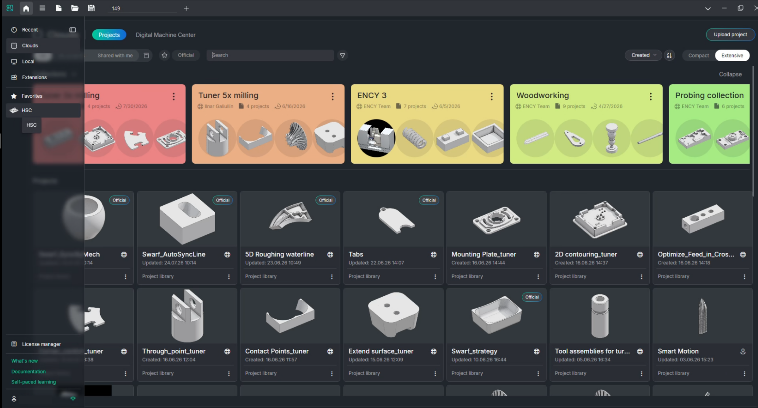
The Home Page has been updated.
The appearance of the Home Page has been revised. You can now organize your projects into collections — grouping related projects together as large color-coded cards at the top of the page, while individual project cards are shown below in a redesigned grid. The left navigation panel has been reorganized for quicker access to Recent, Clouds, Local, Extensions, Favorites sections. See more
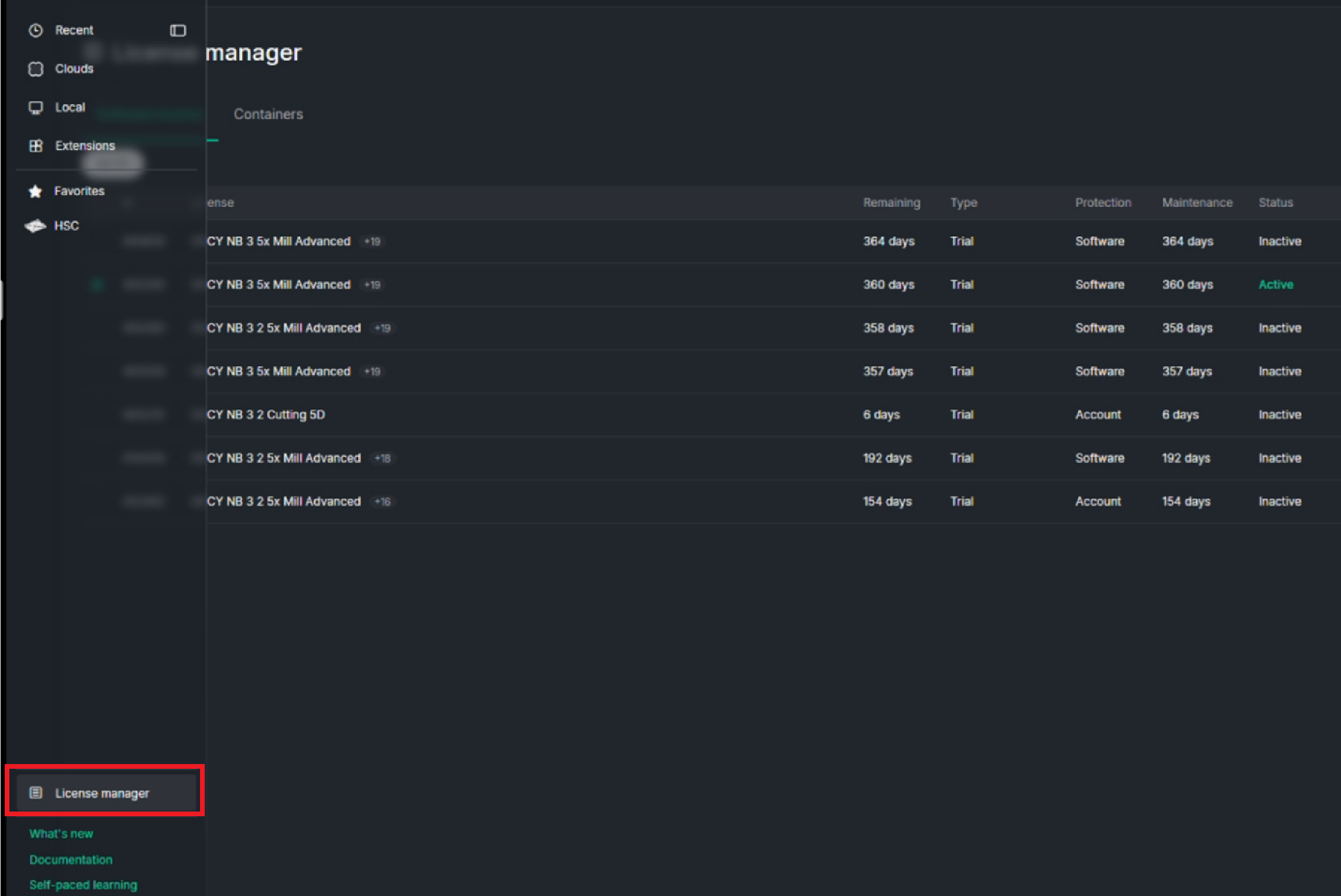
In addition, the License manager is now built directly into the Home Page window instead of opening as a separate window.
The context menu of the inspector has been update.
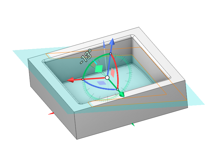
The appearance of elements in the inspector (including dropdown lists, switches, etc.) has been revised. Additionally, parameters on the Setup tab for machines and robots have been reorganized. See more
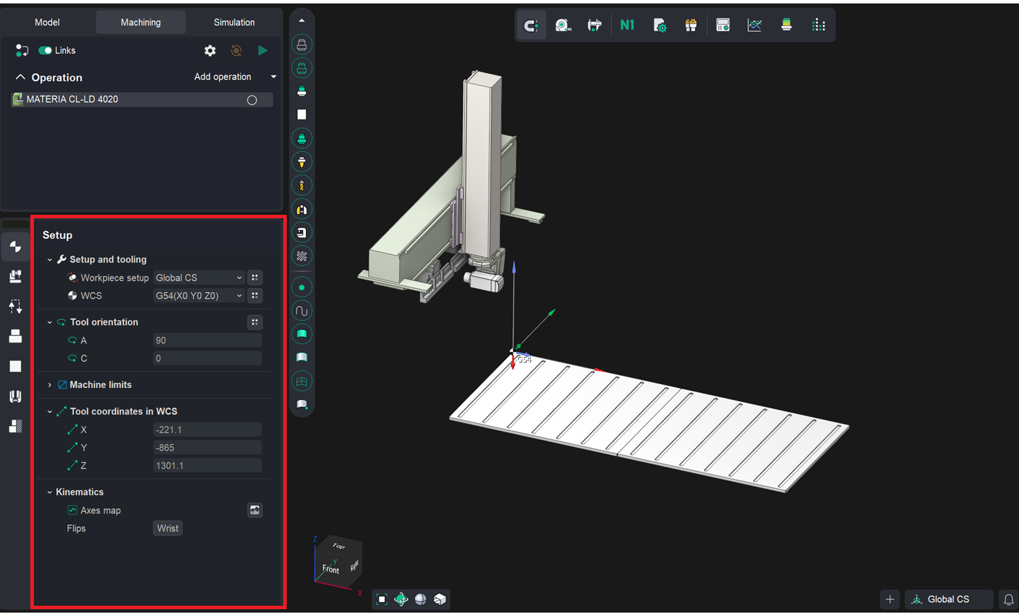
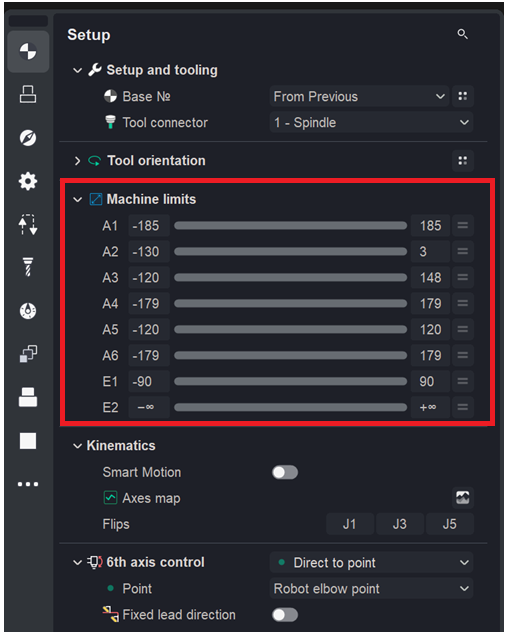
The Machine limits group has been added.
The Machine limits group belongs to the Setup panel and defines reduced per-axis travel limits that are applied when the toolpath and maps are calculated. These values narrow the axis ranges taken from the machine to a smaller working envelope, so that motion is planned strictly within the range acceptable for the current operation. See more
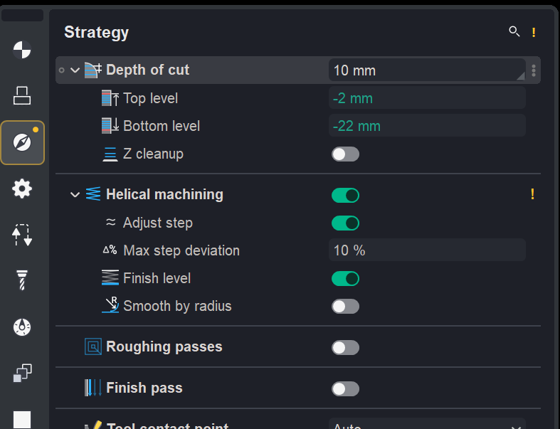
Toolpath recalculation has been optimized.
When parameter changes do not require a full recalculation, the calculated toolpath is preserved. Recalculation updates only the parts affected by the changes, such as transitions, approaches, and retracts.
Changed parameter indicators have been added. The CAM system saves the operation’s parameter state when the toolpath is calculated. If subsequent edits cause the current settings to differ from those used for the calculated toolpath, the operation receives a yellow warning status. The inspector marks changed parameters, their groups, and the corresponding pages, making it easier to locate changes that require recalculation.
Before recalculating, the parameter values used to calculate the current toolpath can be restored.
To hide the hints, open System setup → Additional → Auto-reset toolpath.
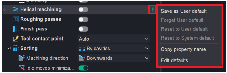
User defaults have been implemented in the inspector.
The inspector’s context menu (opened via the three‑dot button) now includes the following menu items: Save as User default, Forget user default, Reset to User default, Reset to System default, Copy property name, and Edit defaults. See more
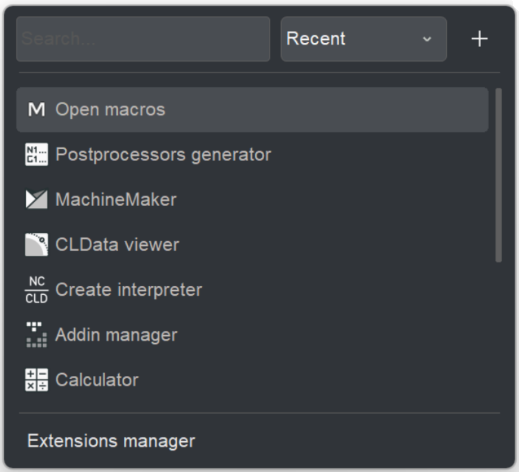
Redesigned the Utilities button of main panel for quick access to built-in and custom tools.
The Utilities button of main panel provides quick access to built-in and user-defined tools directly from the main application window. It combines search, sorting, launching, management of custom utilities, and access to the extensions manager in a single panel. See more
Technology updates
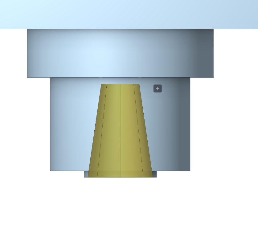
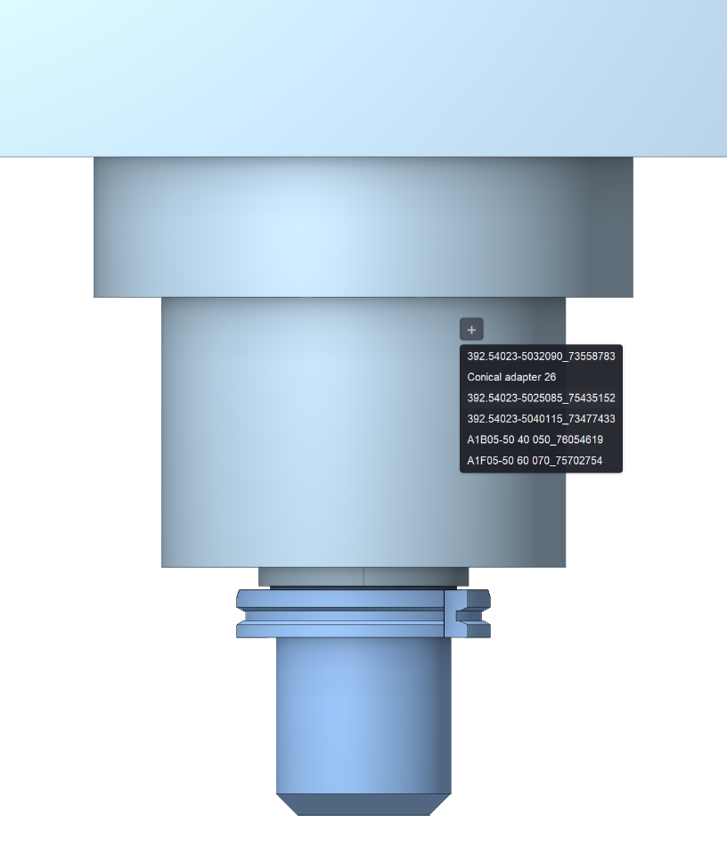
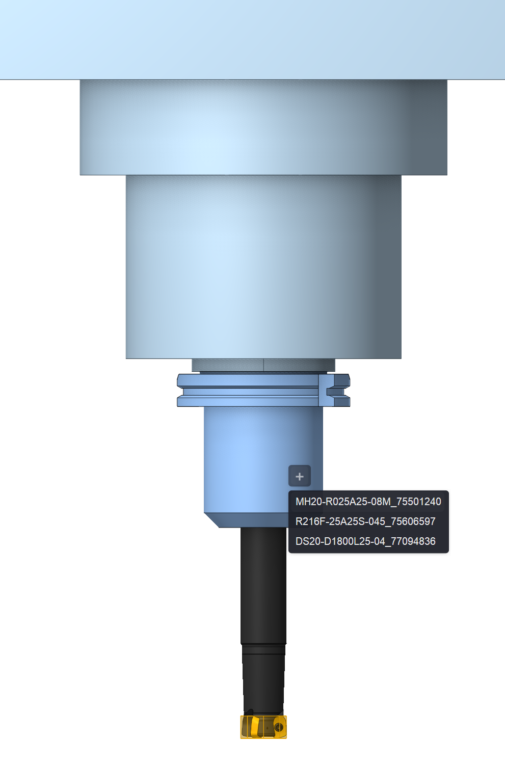
New tool assemblies have been added.
A new mode has been introduced for working with both parametric and 3D tools. It allows you to interactively build a tool assembly in setup mode on the Machining tab — from the mounting seat in the spindle or another machine mounting system to the tool, including various toolholders. See more
A new Combo Finish operation has been added.
Strategies:
• Plane (Finishing);
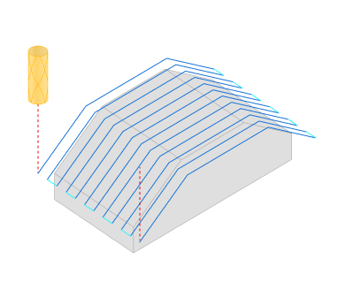
• Waterline;

• Scallop;
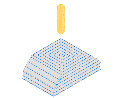
• Plane + Waterline;
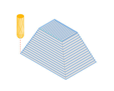
• Scallop + Waterline.
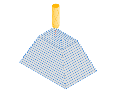
Advantages:
• Support for generating helices for waterline passes (helical machining).
• In combined strategies, gentle and steep areas are processed using different strategies. This ensures a uniform scallop pattern on the surface and improves cutting conditions.
• Combined strategies feature smoothing/merging of machining zones based on the Smooth distance parameter. This helps produce a more solid toolpath with fewer unnecessary passes and transitions.
• Intelligent toolpath merging for combined strategies has been implemented.
• The calculation process is fully parallelized.
This operation can replace outdated legacy operations and address associated issues. See more
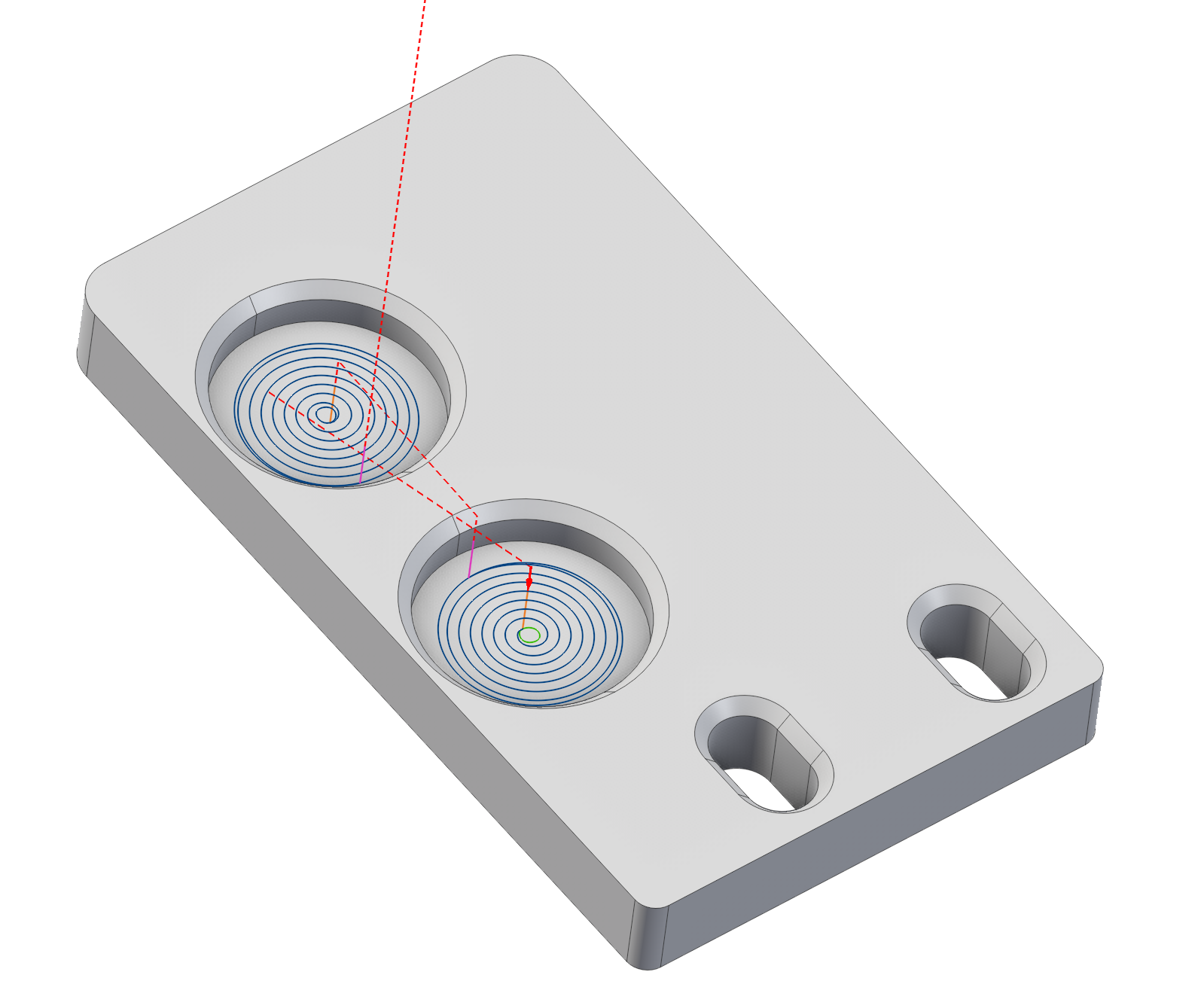
The Combo Finish operation with the Plane+Waterline strategy replaces the legacy Complex operation, offering improved surface quality and reduced machining time.
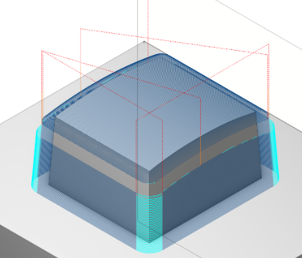
Complex
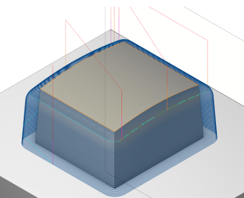
Combo Finish (Plane+Waterline strategy)
The Finishing Waterline operation lacks a defined start point, which may cause tool collision or gouging between adjacent parts. The new Combo Finish operation now includes a user‑definable start point in all strategies, enabling more flexible and controlled machining.
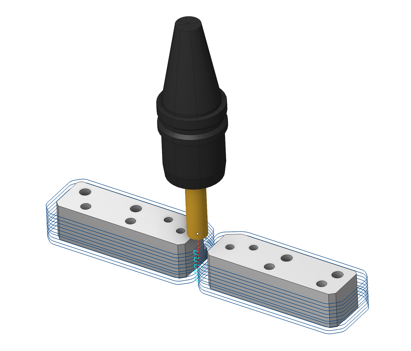
Finishing Waterline ( Unsatisfactory tool entry into the workpiece )
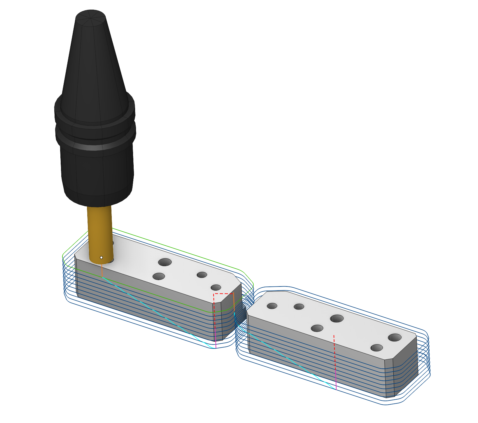
Combo Finish (Allows shifting the
start point
to ensure smoother tool engagement between two parts.)
The Finishing Waterline operation currently lacks Spiral machining capability. As a result, it is not possible to perform the intended machining process using this strategy.
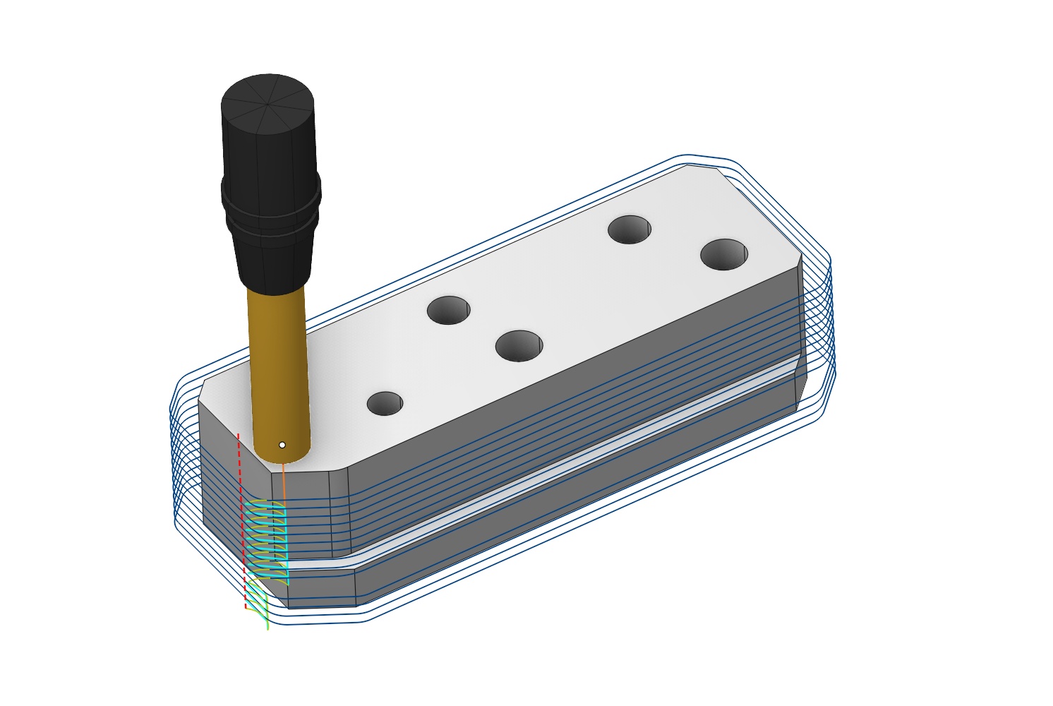
Finishing Waterline (Spiral machining is not supported)
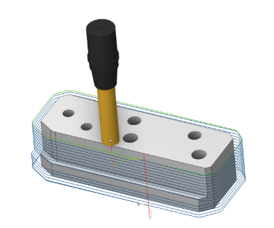
Combo Finish (Allows spiral machining)
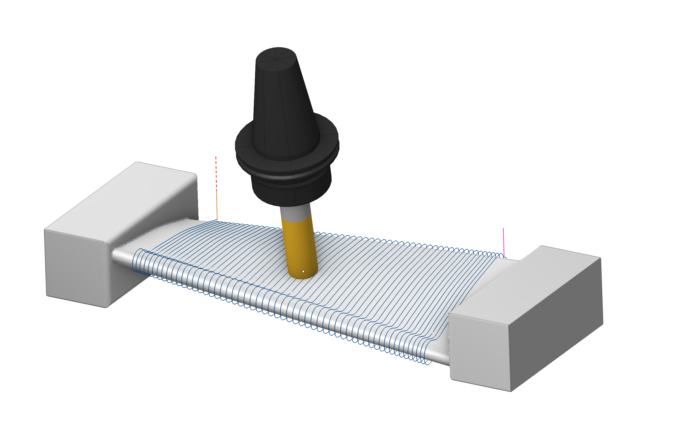
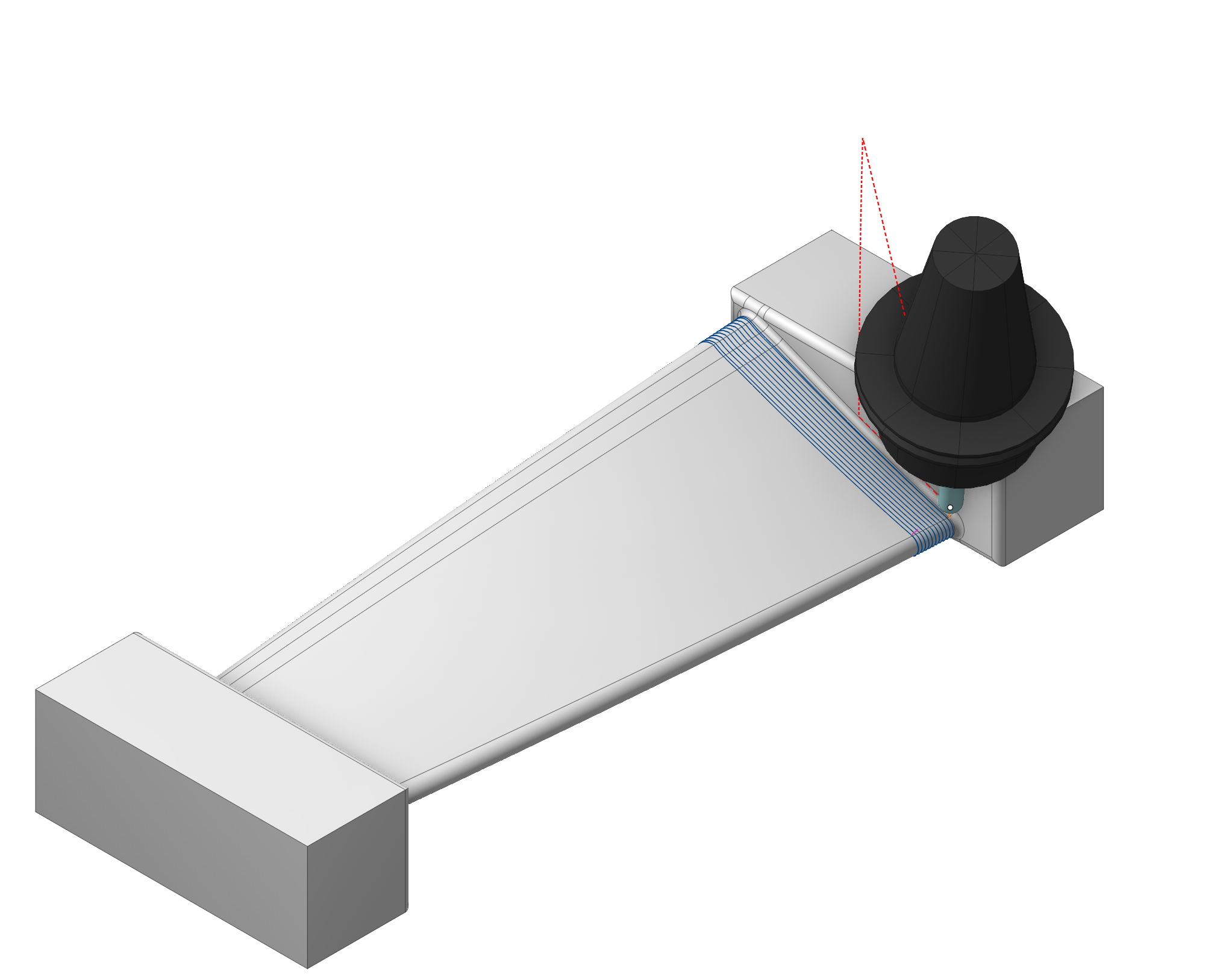
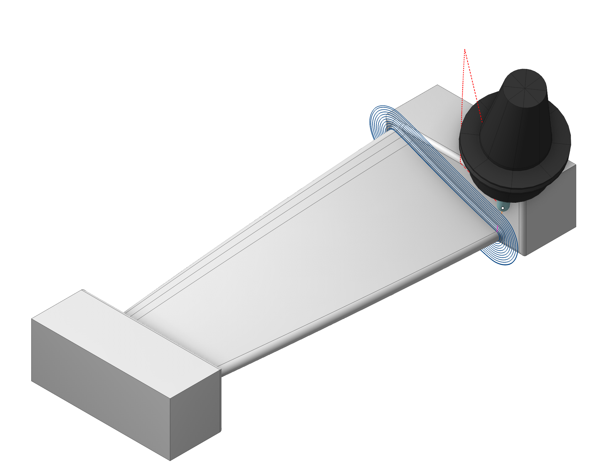
A new Blade Machining operation has been added.
The specialized blade machining module introduces dedicated processing strategies for key structural elements: Blade, Root zone of blade, Hub. This enables optimized toolpaths and improved surface quality for each critical area. See more
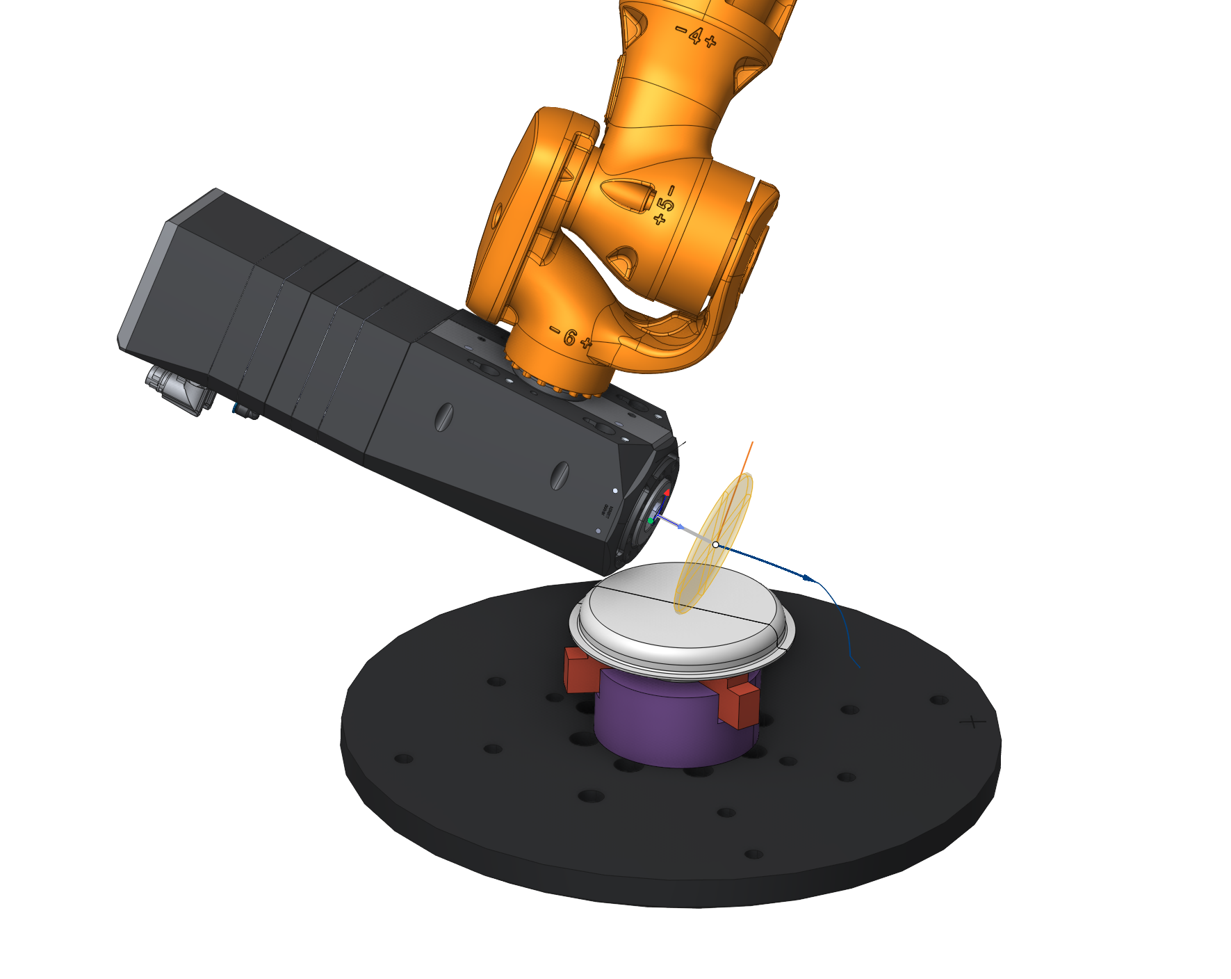
A new Contour Polishing operation has been added.
The operation finishes part walls and edges along defined contours using the side of a disc tool. See more
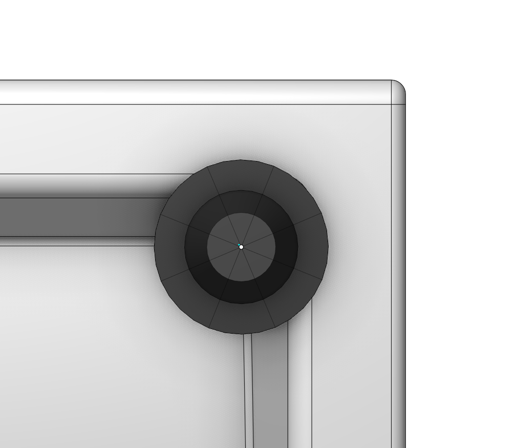
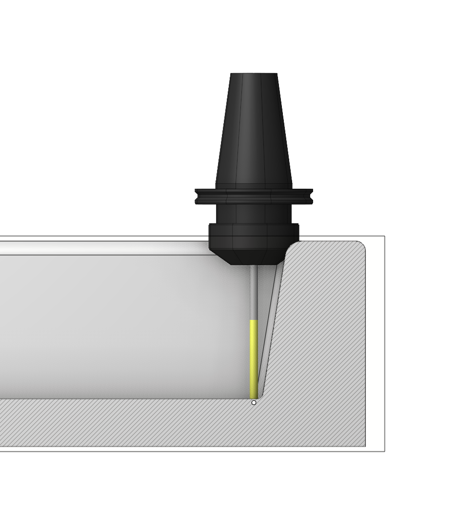
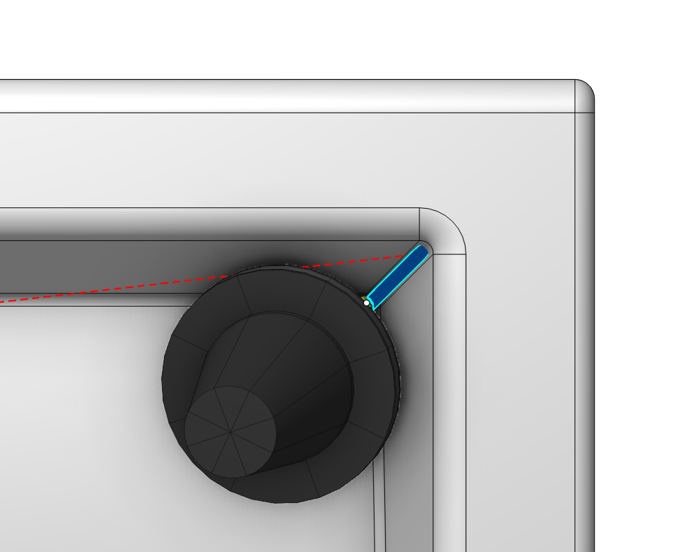
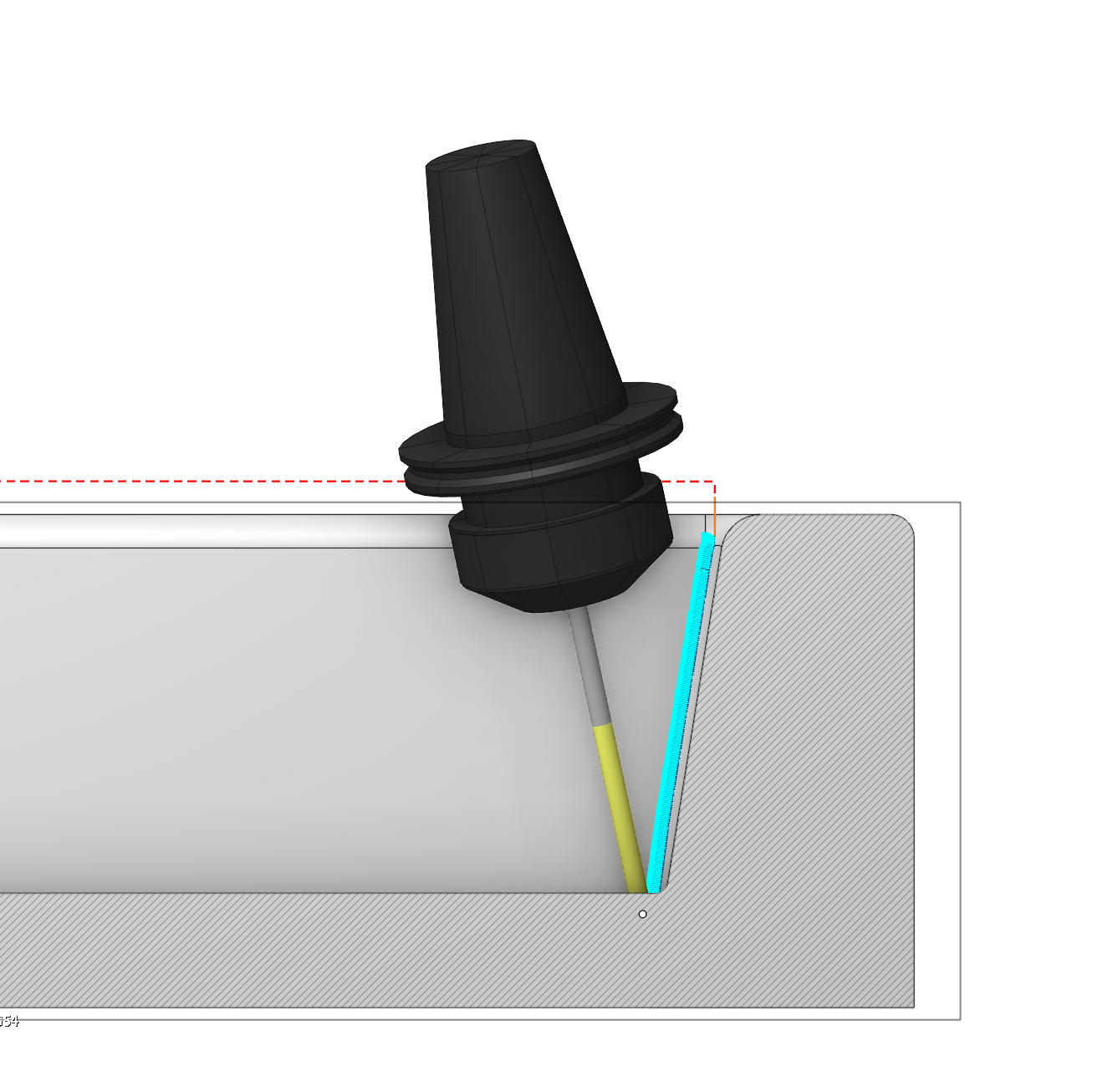
A new option has been added to the Check Holder: Adaptive tilting, Check links.
Unlike the Side Tilting option, this feature enables simultaneous angular deviation along two axes. This capability allows for the conversion of 3‑axis machining to 5‑axis machining at various angles. See more
The Check Links function enables angular deviation during transitions between machining (cutting) passes.
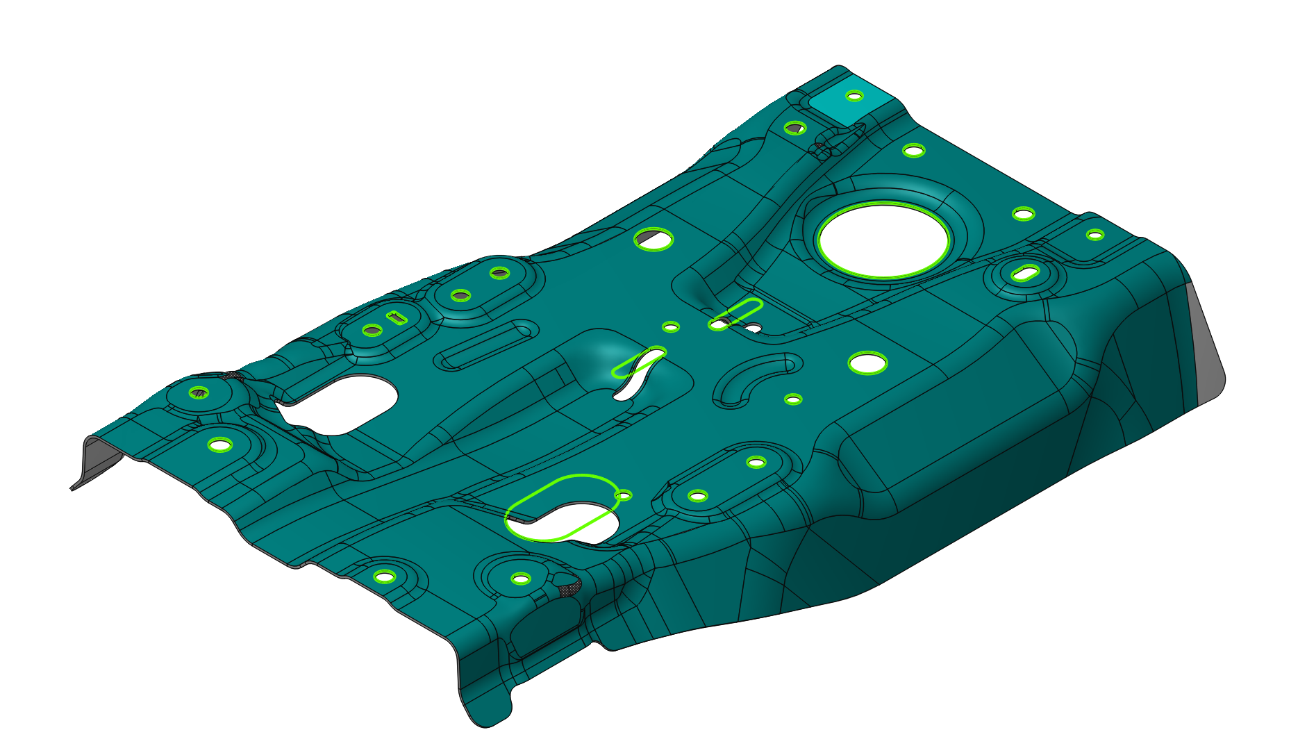
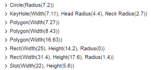
The Recognize features option has been added for the 6D Contouring operation.
The Recognize features option has been added for the 6D Contouring operation ( See more ). It allows recognizing the following constructive elements: Circle, Rectangle, Rounded Rectangle, Slot, Hexagon, and Keyhole. This feature replaces primitive motion commands (line segments, arcs) in NC programs with high‑level constructive elements to improve code readability, compactness, and enable advanced post‑processing features. See more
The Smart Motion option has been improved.
Smart Motion enables robot trajectory generation for 5D and 6D points without requiring a robot axes map. The resulting trajectory stays within axis limits and includes singularity and collision avoidance. Additionally, the trajectory can be fine-tuned using the robot axes map.
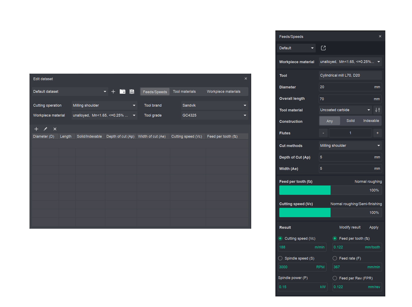
The Feeds/Speeds calculator has been redesigned and enhanced.
In previous software versions, the calculator provided basic automatic calculation of cutting conditions. For instance, users could input the cutting speed and feed per tooth to automatically derive the spindle speed and table feed rate. The new version of the calculator introduces a comprehensive suite of tools for automated cutting condition calculation. See more
The system now accounts for critical machining parameters, including:
• tool type (Solid or Indexable);
• workpiece material;
• and other relevant factors.
This enhanced functionality enables users to build and maintain a custom library of cutting conditions. By default, calculations are performed using established industry databases from leading manufacturers: Walter, Kennametal, and Sandvik.
Improvings in Corner control.
Added new Action Type options: Adjust Feed, Adjust Power, and Adjust Feed & Power. Feed adjustment now supports values above 100%, enabling corner acceleration. Power can be controlled independently or alongside feed. See more
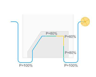
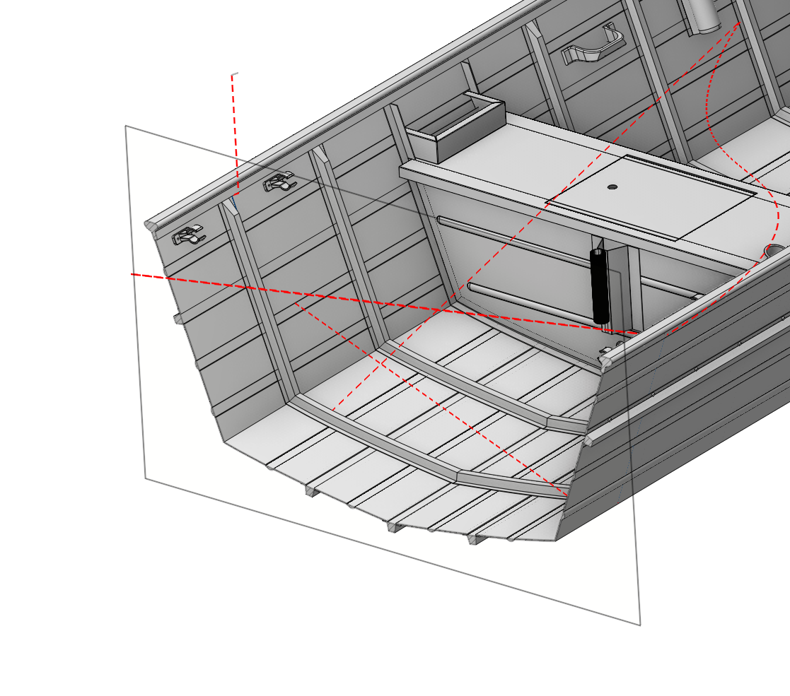
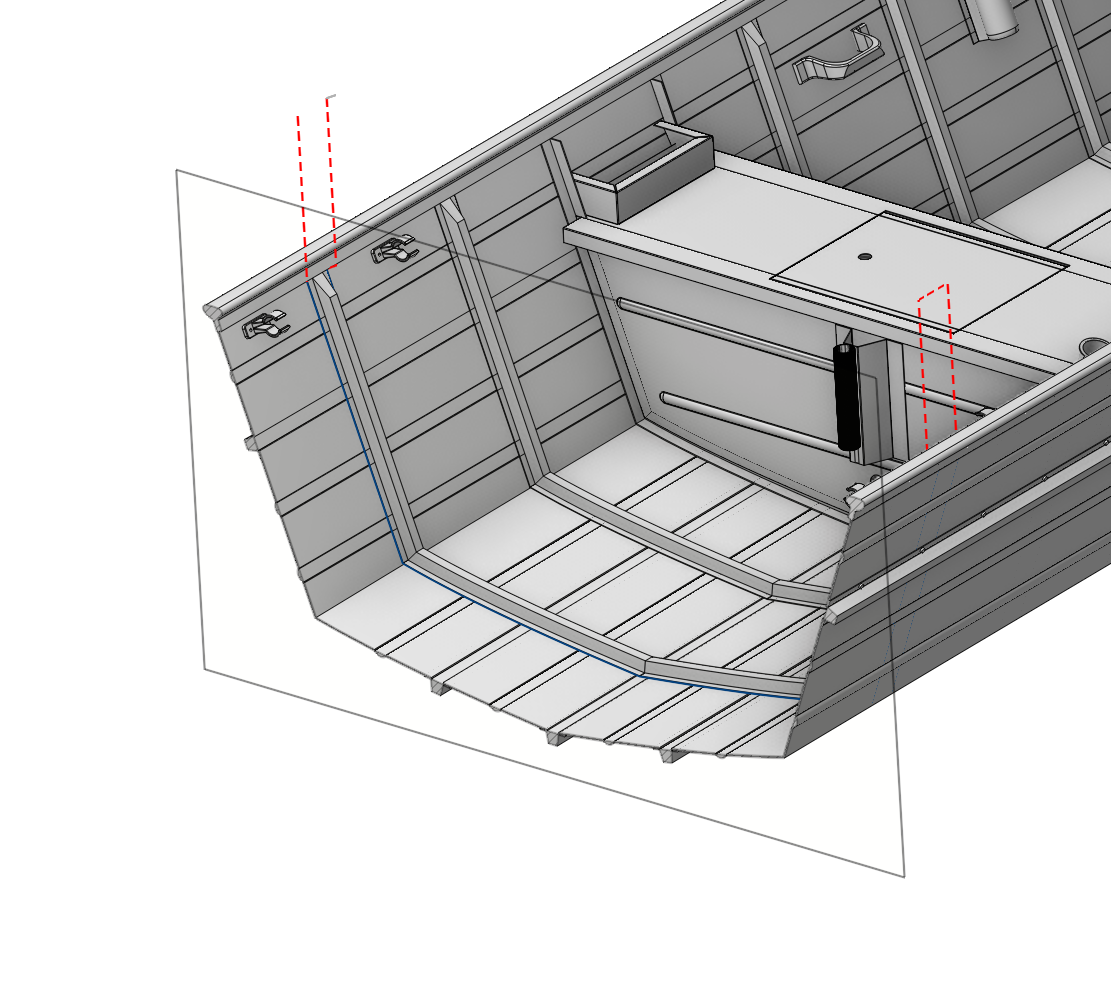
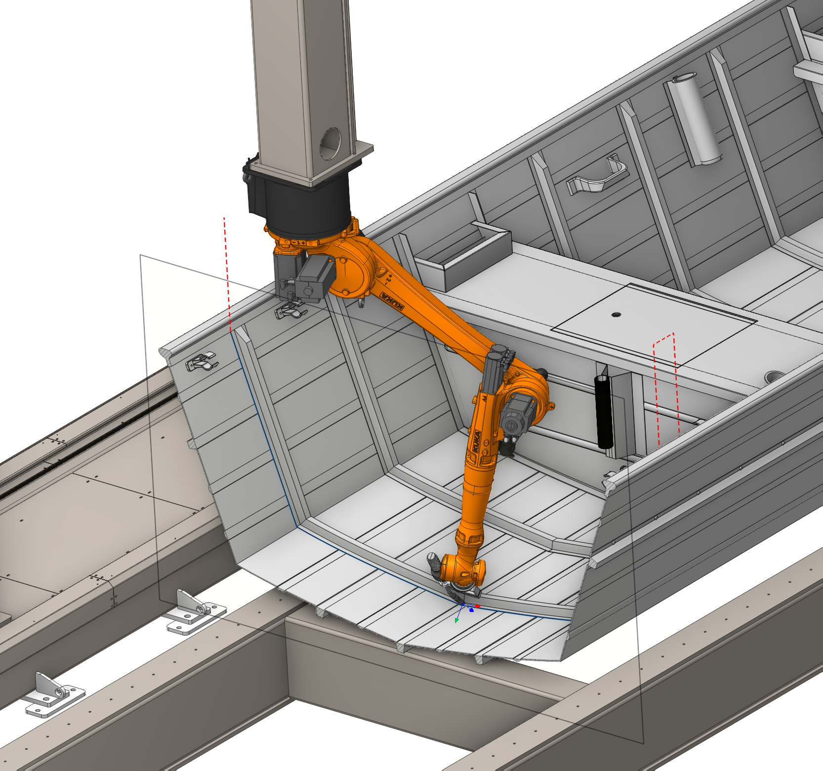
Pullback option has been added to the Welding 6D.
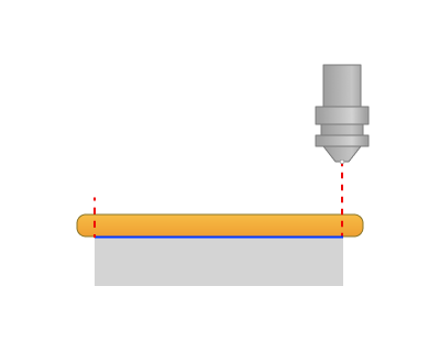
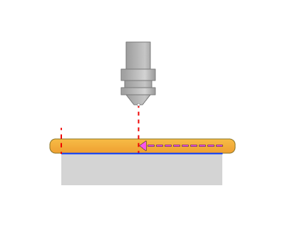
Available for several welding types. When enabled, the tool travels back along the finished weld by a configurable distance before it lifts off, so residual energy stays over already-welded material and does not mark the clean surface — useful for laser welding, where the beam may not switch off instantly. See more
New precise format for exporting simulation result
Simulation results can now be saved in the new precise .camsr format and loaded into another project as a workpiece, preserving the exact model instead of losing detail through STL. Find it in the simulation result export dialog and via the new Sim result button on the Workpiece tab. See more
Support Generator has been added.
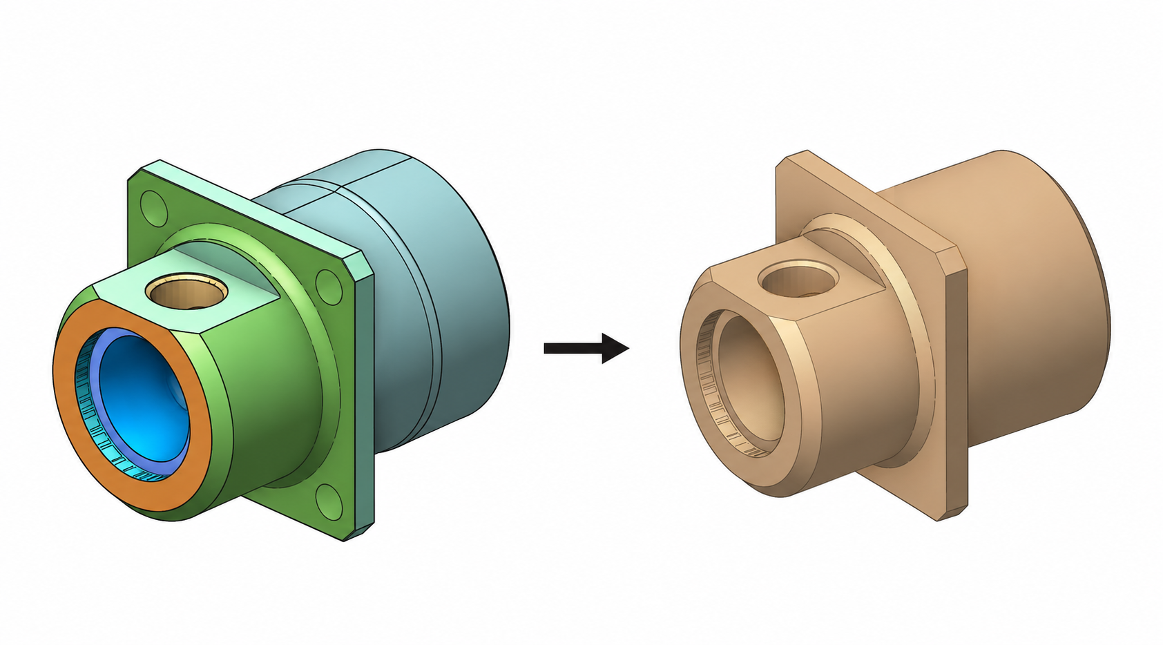
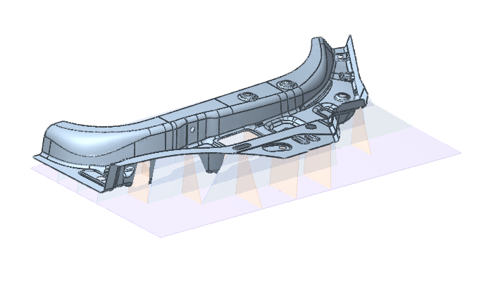
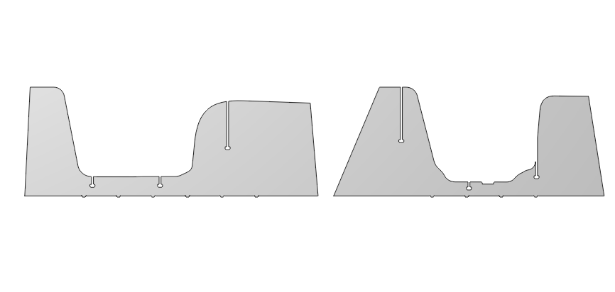
Support Generator is a new extension that builds custom fixtures for holding parts during machining, straight from a 3D model. Choose a build plane, tune the rib grid interactively, and watch the fixture take shape in a live preview. A single click turns it into ready-to-manufacture geometry — complete with the flat-sheet nesting layout for laser cutting. Available in the ENCY Extension Store.
Additive manufacturing updates
Improvings in Non-planar slicing operation
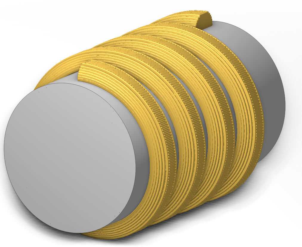
Radial slicing strategy
Added a new Radial slicing strategy — slicing is performed by cylindrical surfaces around a specified rotary axis with a constant radial step between layers. The strategy supports parts with any angular extent around the rotary axis:
• fully closed (360°) — rings, cylindrical sleeves, shells;
• with an angular gap (<360°) — turbine blades, propellers, impellers;
• helical (>360°) — augers, spiral parts.
Gap to prevent overlapping
In a Non-planar slicing operation, you can now specify a gap at the seam of closed contours to prevent line overlap, using Gap to prevent overlapping. See more
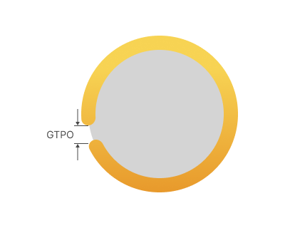
GTPO - Gap to prevent overlapping.
Custom angle sequence for infill.
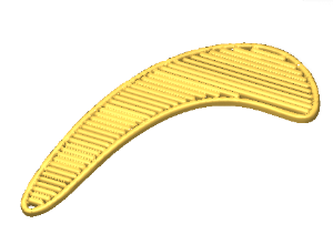
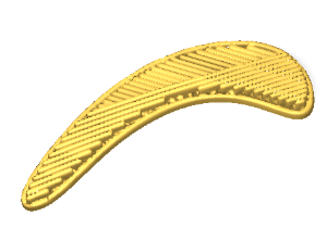
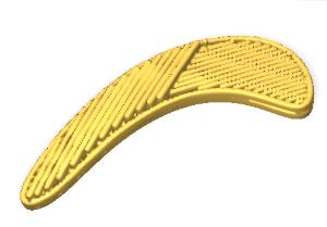
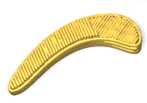
Added the By sequence of angles option to Alternate lines direction, which lets you define a custom sequence of angles for infill direction across layers. See more
Example: (0,45,90,135) means layer 1 = 0°, layer 2 = 45°, layer 3 = 90°, layer 4 = 135°, layer 5 = 0° and so on:
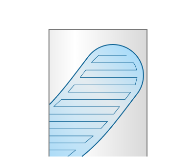
Zig Zag infill pattern.
Added a new Zig Zag infill pattern. Each model layer is divided into regions that can be filled with a continuous zigzag toolpath. A separate toolpath is generated for each region: a contour containing five regions produces five zigzag toolpaths, while a single-region contour produces one continuous toolpath. See more
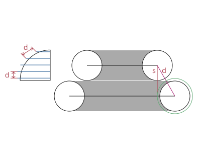
Power function
Added a Power function option to the Non-planar slicing operation. It works the same as in the Cladding 5D operation. See more
Maximum layer time
Added a Maximum layer time parameter for additive operations that automatically scales up the working feed when a layer takes too long — useful for concrete 3D printing to avoid cold joints. See more
Design module enhancements
Design in 3D mode.
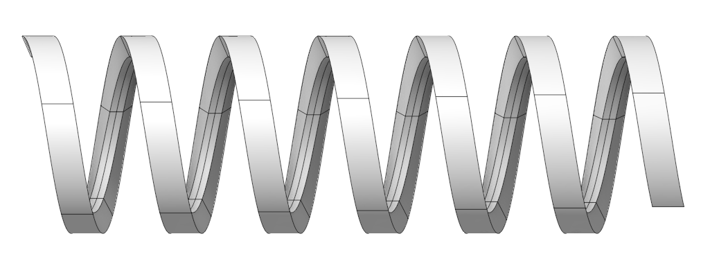
Added a Сoil.
Generation of a 3D solid by extruding a sketch along a helical trajectory (unlike the Sweep operation, explicit creation of a helical guide curve is not required).
See more
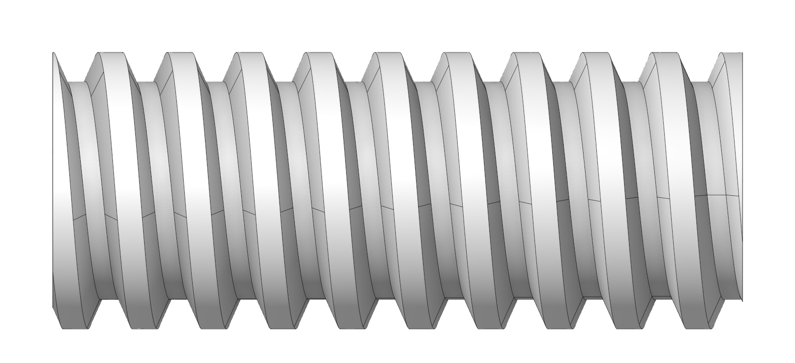
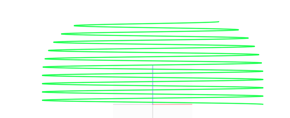
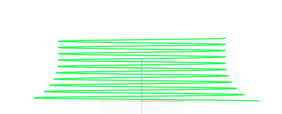
A new option has been added for Helic: Start Runout and End Runout.
Radius Exit for the Start diameter / End diameters. See more
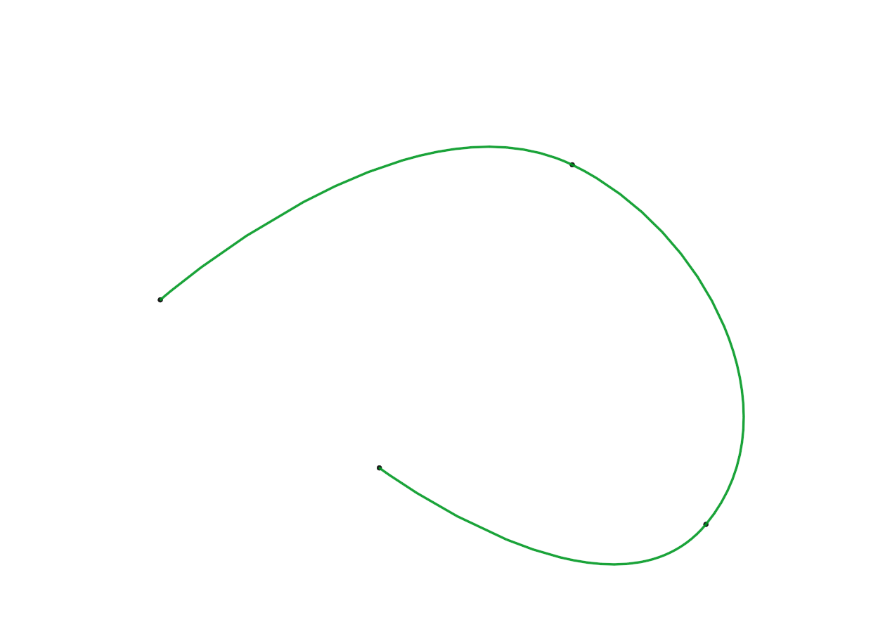
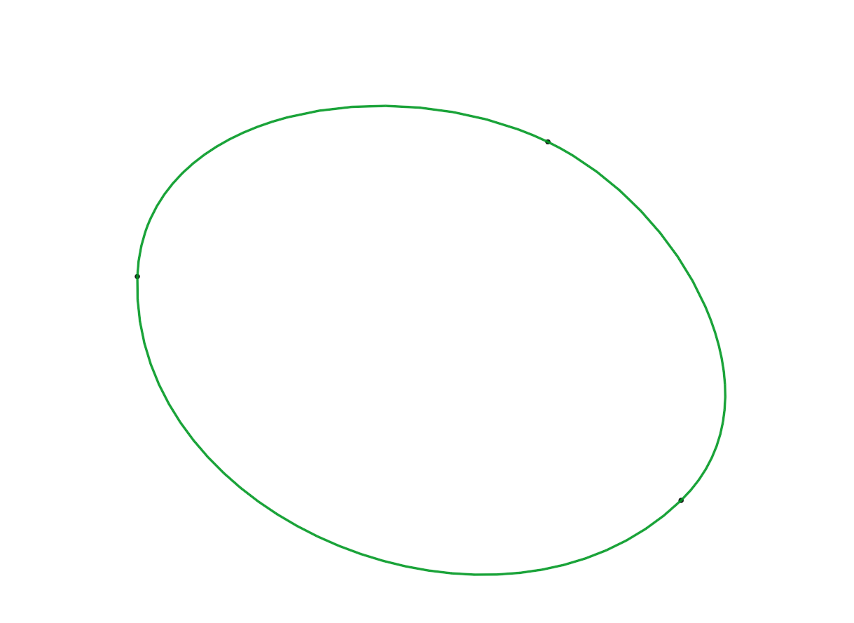
A new option has been added for splines: Closed.
New Nesting Functionality
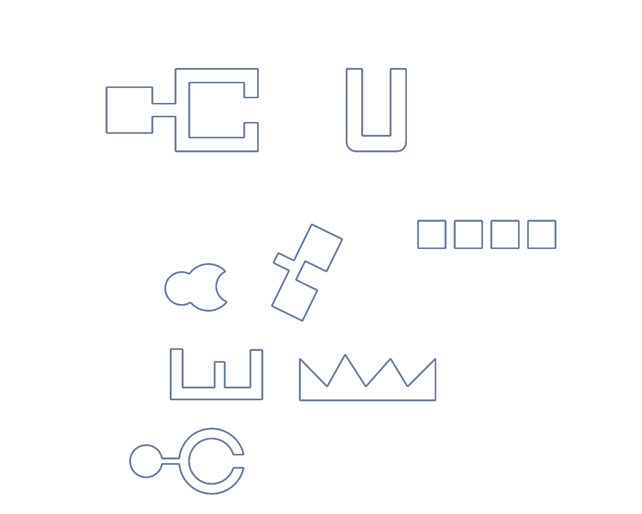
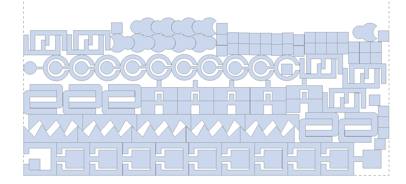
The new Nesting tool is available from the Model tab. Right-click a sheet and select Create nesting to automatically arrange selected parts and optimize material usage.
The Nesting tool automatically arranges selected parts on a sheet to optimize material usage and reduce waste. Configure sheet dimensions, spacing, margins, part copies, rotation, mirroring, grain direction, and placement rules before generating the layout. See more
3D View Controls
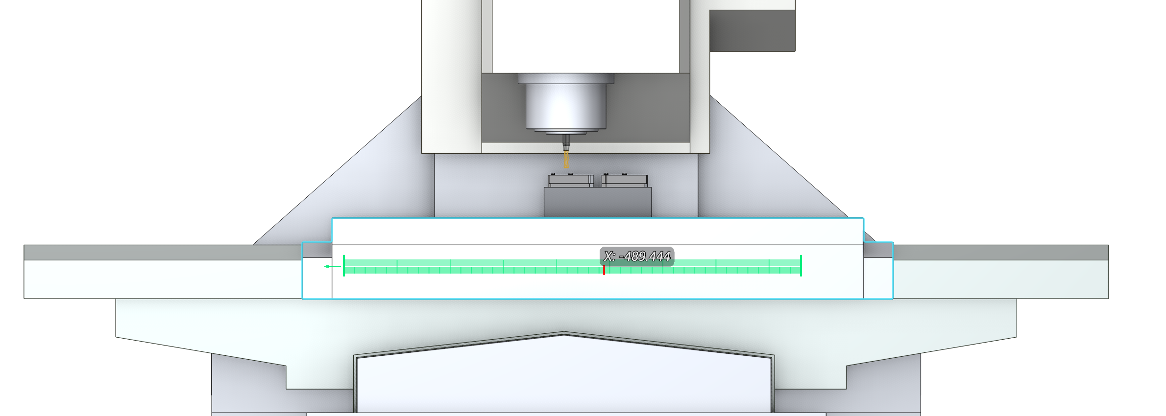
Added an interactive linear axis ruler.
It appears when you drag a machine node along a linear axis in the 3D view. The ruler displays the current axis coordinate, its travel limits, and provides precise position control.
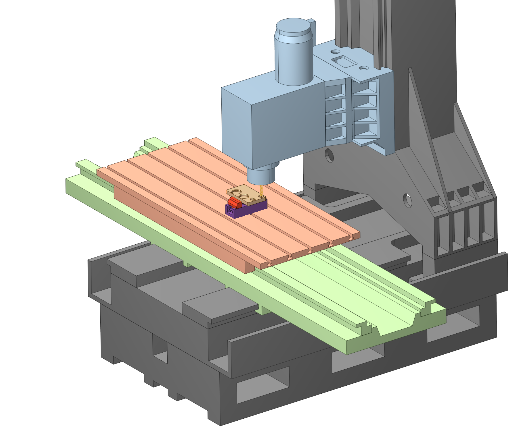
Updated Machine Display Settings in the 3D view.
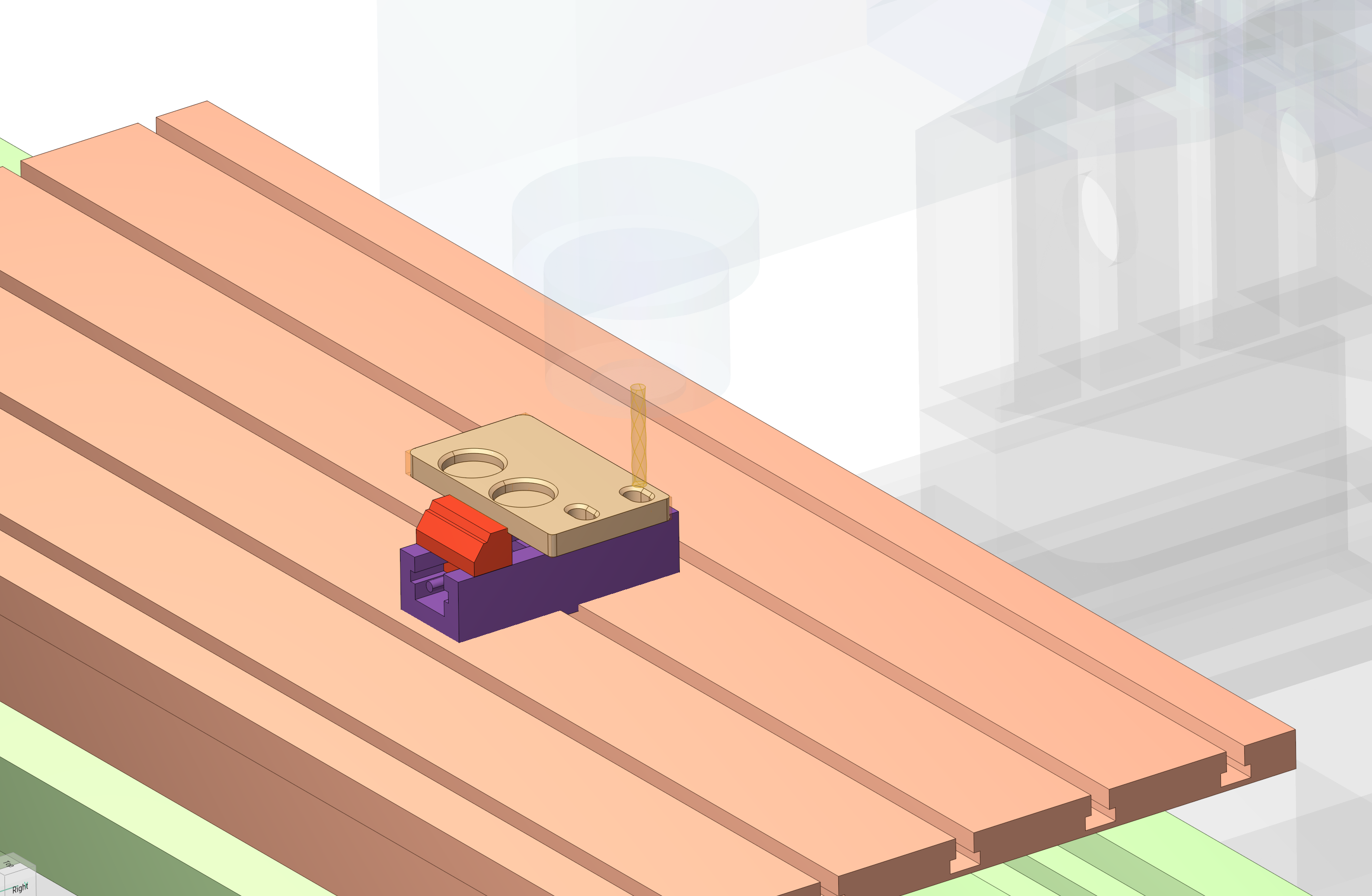
The Machine Visibility Settings popup helps keep the working area visible and convenient during setup and simulation. It lets you select a machine surface material, such as Gunmetal or Industrial, and keep a selected machine component visually stationary while the remaining components move relative to it. You can adjust the opacity of machine nodes to reveal internal mechanisms or the machining area, and control the visibility of individual nodes in a tree where hovering over a node highlights it in the 3D view.
Interactive Machine is available when Expert Tools (Additional tab of the settings) is enabled. See more
Updated Toolpath Display Settings in the 3D view.
The new Toolpath Display Settings popup makes the machining trajectory easier to inspect during preparation and simulation. You can enable feed-type coloring or use a single toolpath color, and adjust the line width to keep the trajectory readable at any zoom level.
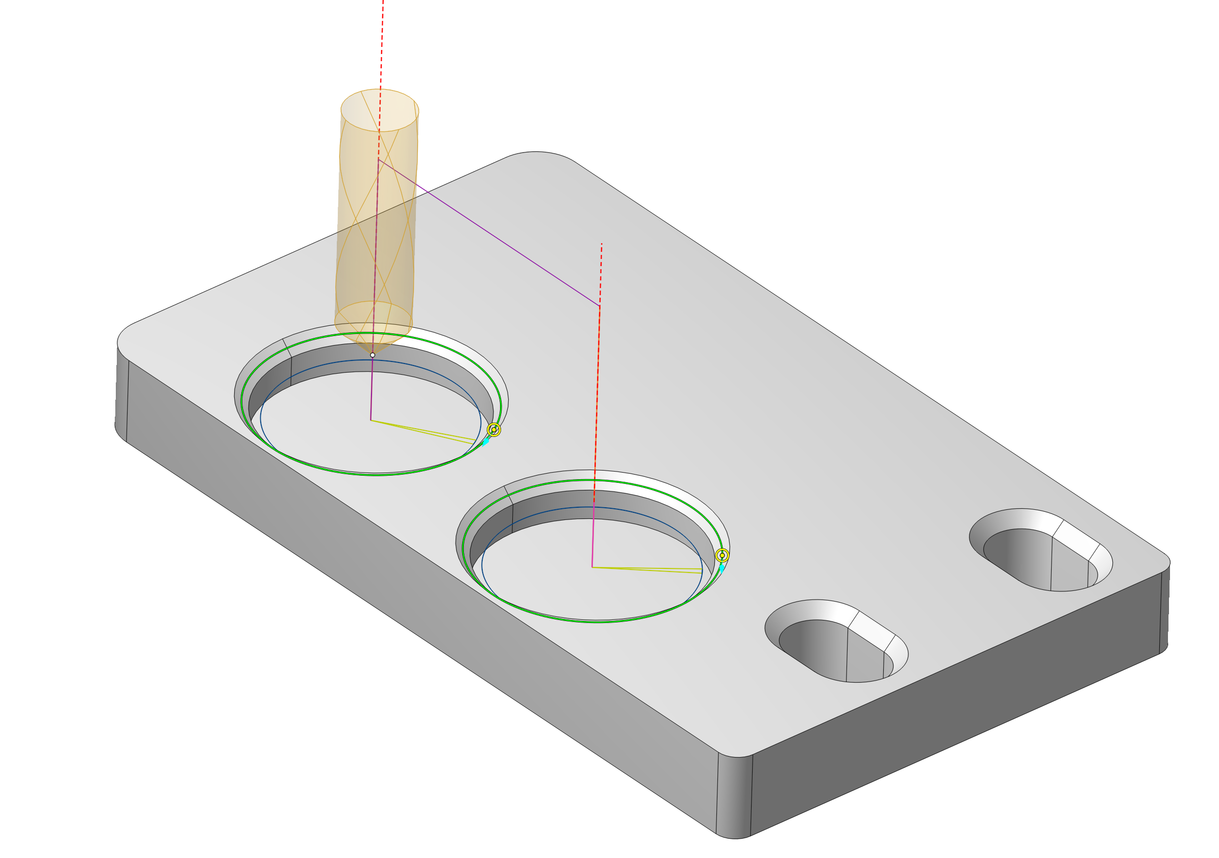
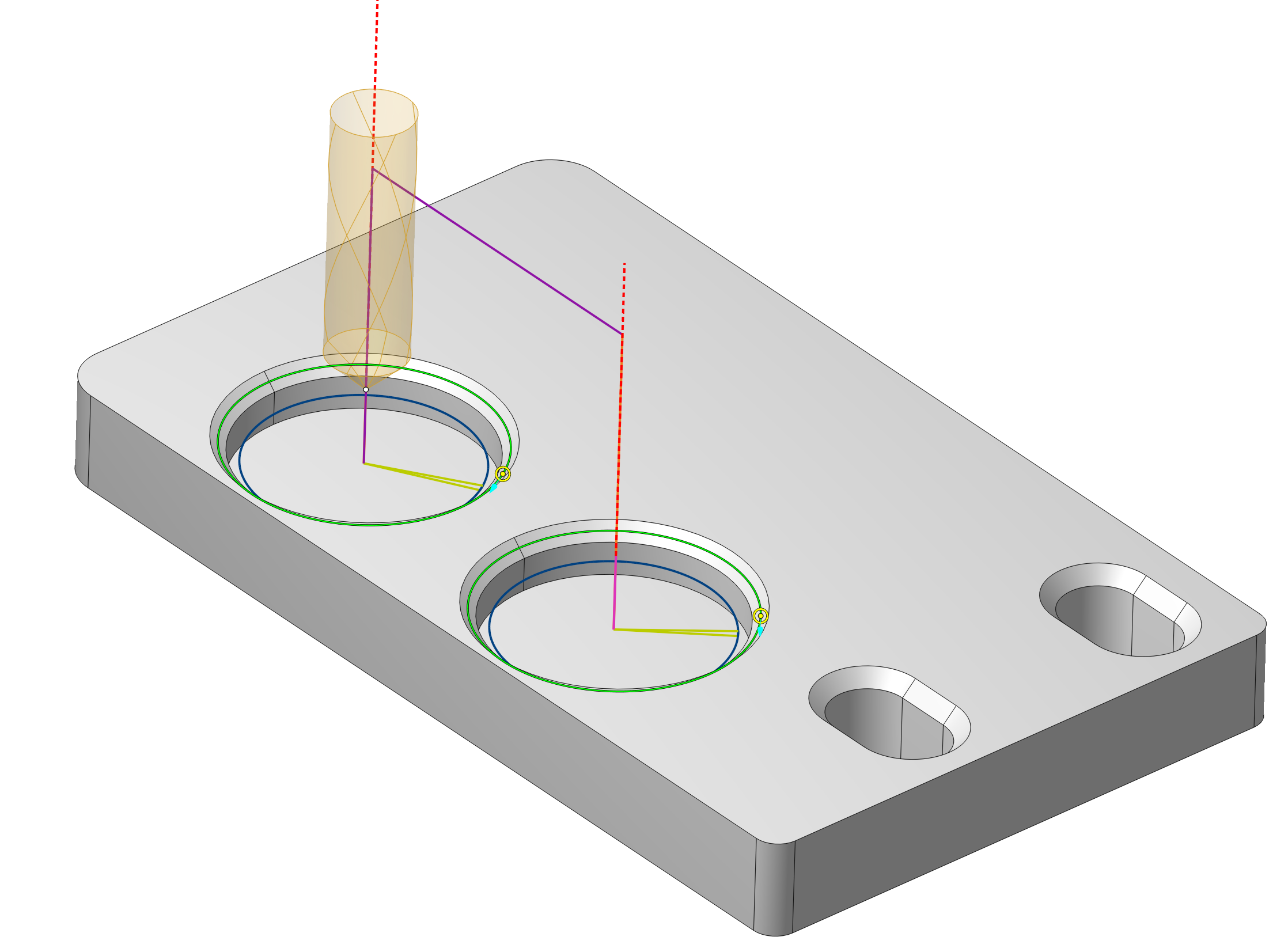
During simulation, select which part of the current operation's toolpath is shown: the full trajectory, the path already completed, the remaining path, or a configurable segment before, after, or around the current tool position. The rest of the program remains visible as a ghost layer. You can also hide rapid, approach/return, and link moves to focus on cutting passes. Surface normals and toolpath point markers can be displayed to verify the orientation and structure of multi-axis toolpaths. These overlays follow both the selected move visibility settings and the current playback trace.
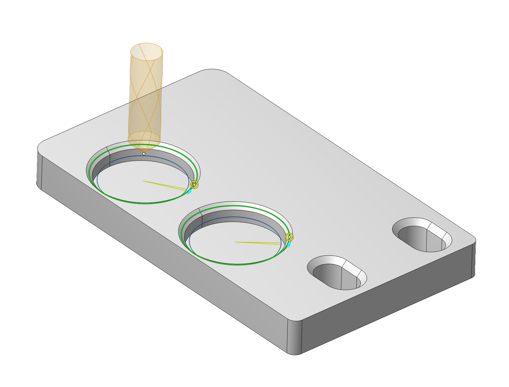
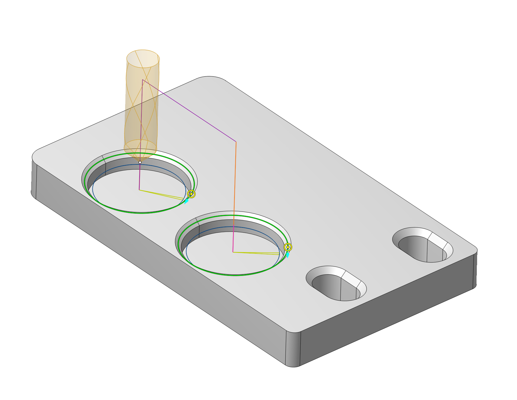
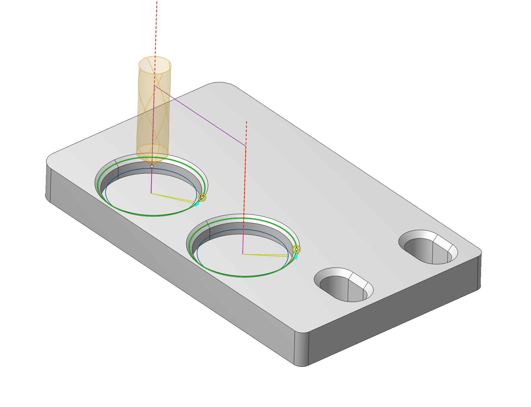
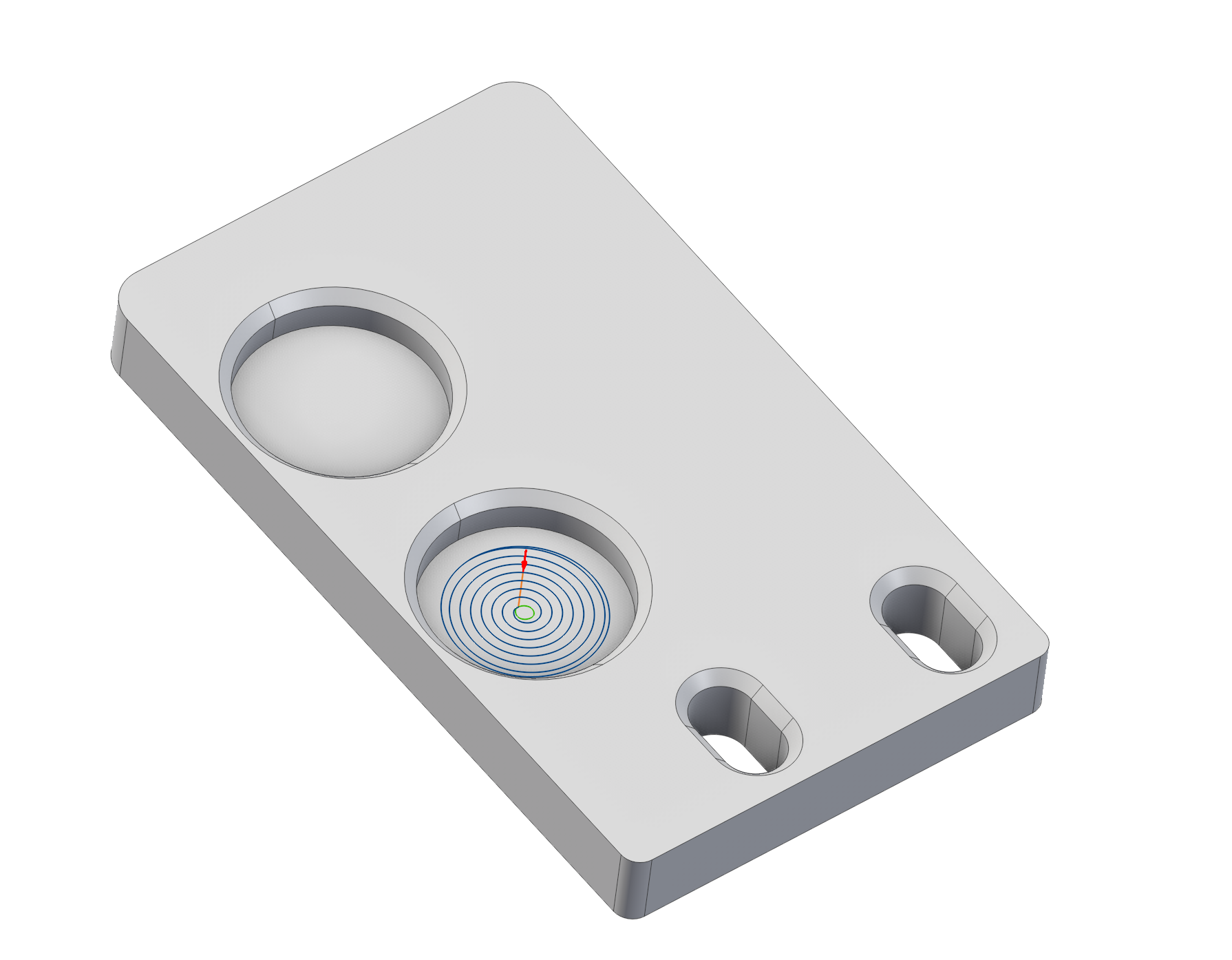
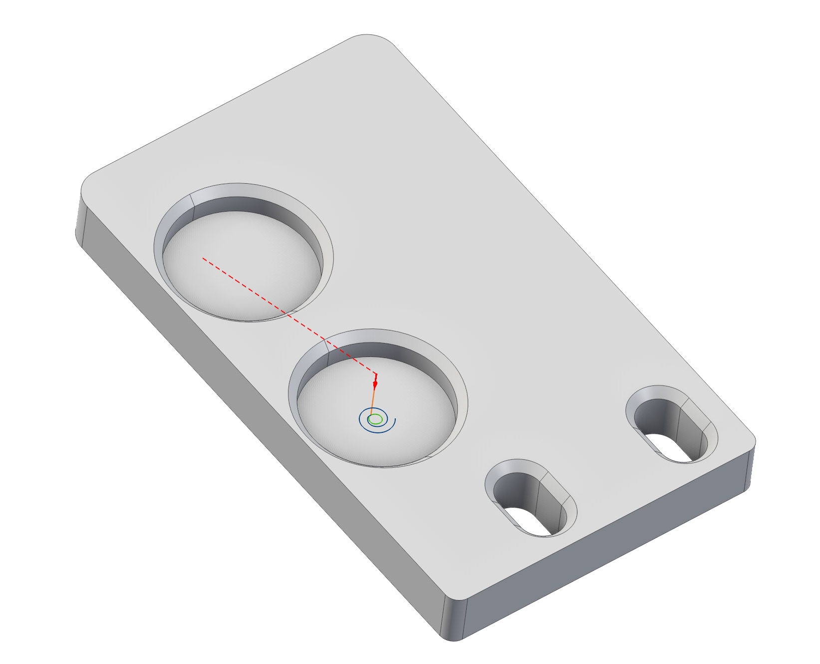
The Simulation tab now includes additional options for visualizing the toolpath. Configure which parts of the trajectory are displayed to focus on the current machining stage and inspect the operation more clearly.
• Current layer — shows the current toolpath layer.
• Full toolpath — displays the entire toolpath.
• From start — shows the toolpath from the beginning to the current tool position.
• To end — shows the remaining toolpath from the current position to the end.
• Tail — displays a limited toolpath segment around the current position.
• Tail ahead — displays a segment ahead of the current tool position.
• Tail both ways — displays segments before and after the current tool position.
Updated Display Mode Settings in the 3D view.
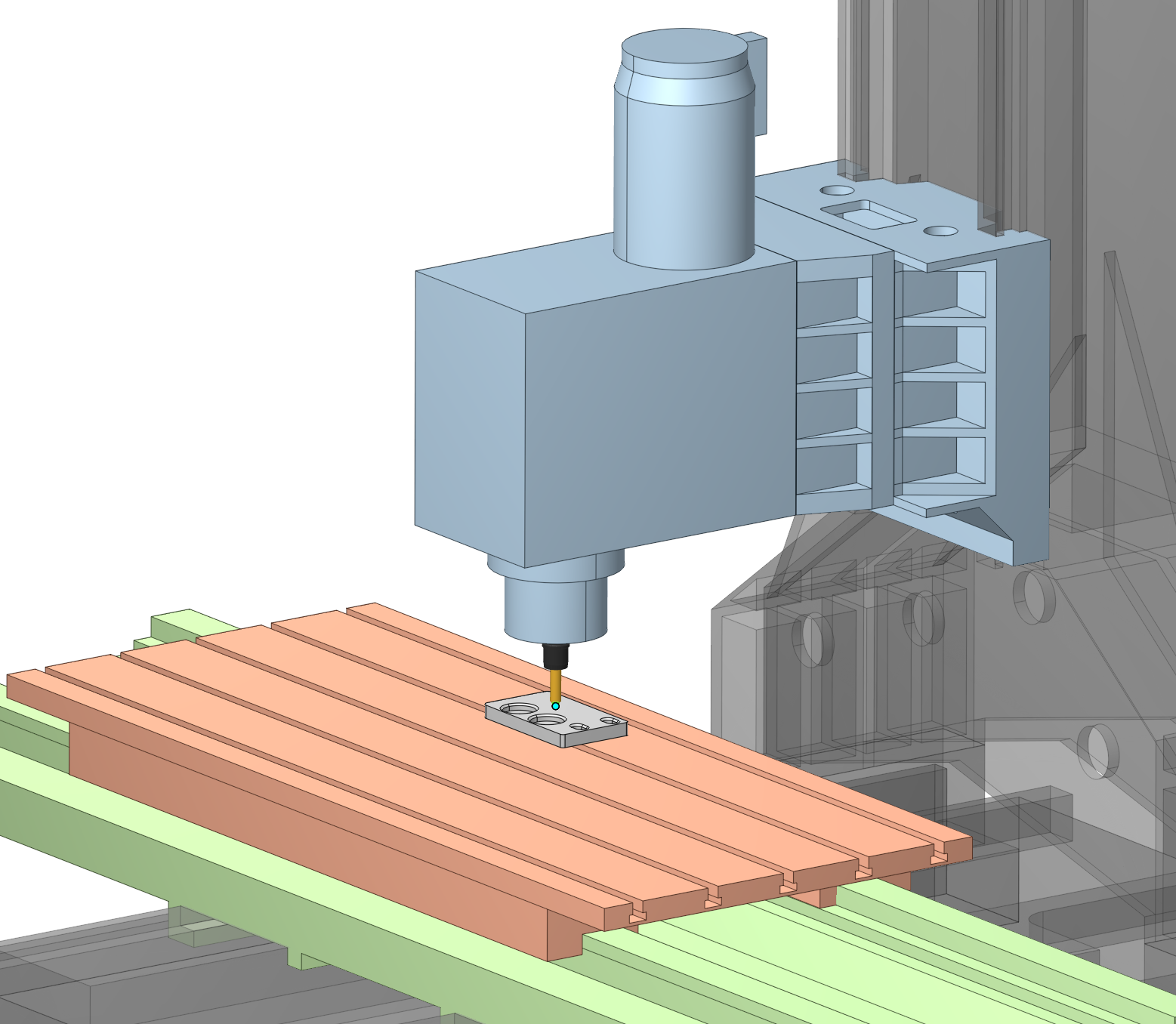
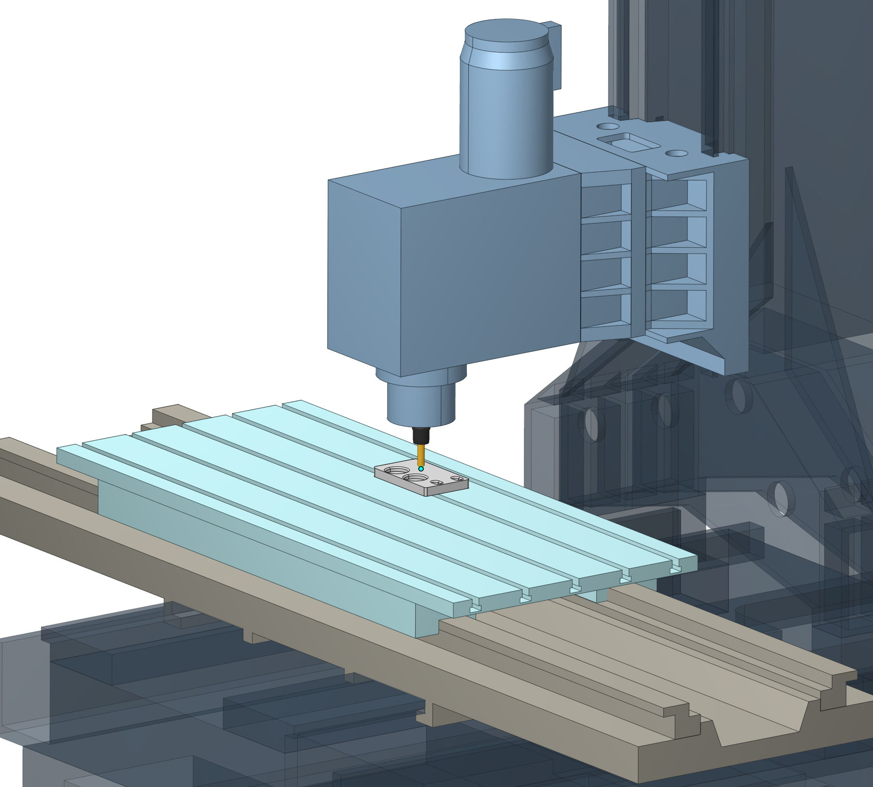
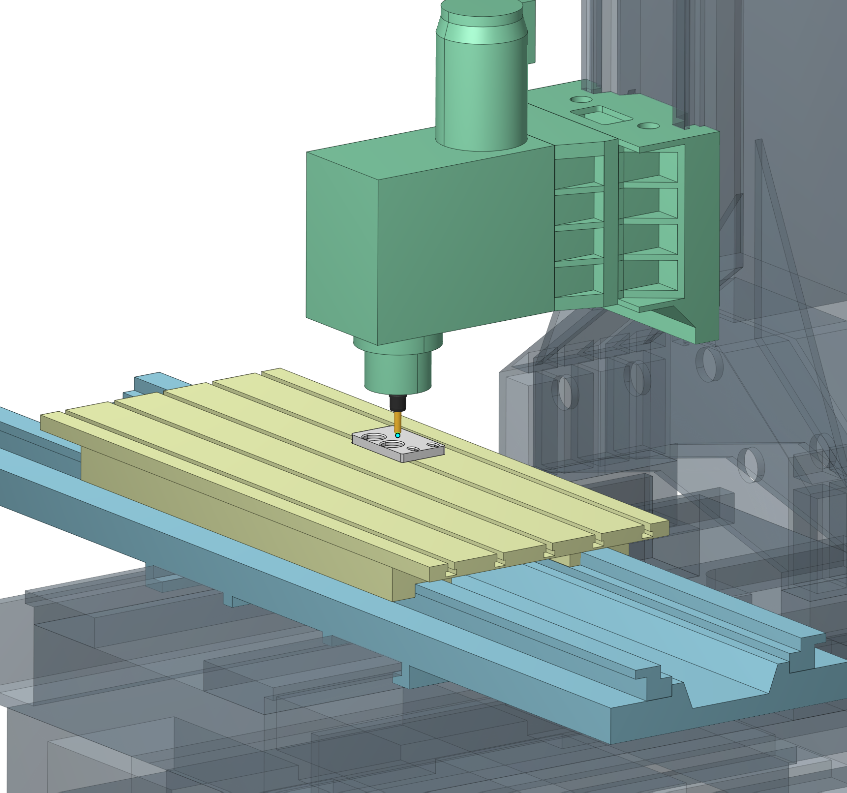
The Display Mode popup provides quick control over the visual presentation of the 3D scene. You can switch between shaded, shaded-with-edges, and wireframe rendering modes to choose the most convenient way to inspect the machine, part, and surrounding geometry.
The popup also lets you enable ambient occlusion for improved depth perception and a ground plane for clearer scene orientation. Equipment color schemes can be applied to highlight the machine kinematics: each kinematic link receives a distinct contrasting color, while static components remain neutral. Project Colors preserves the original model colors, while Gunmetal and Restrained provide alternative industrial palettes. Robot manipulators retain their native manufacturer colors in every scheme.
Other updates
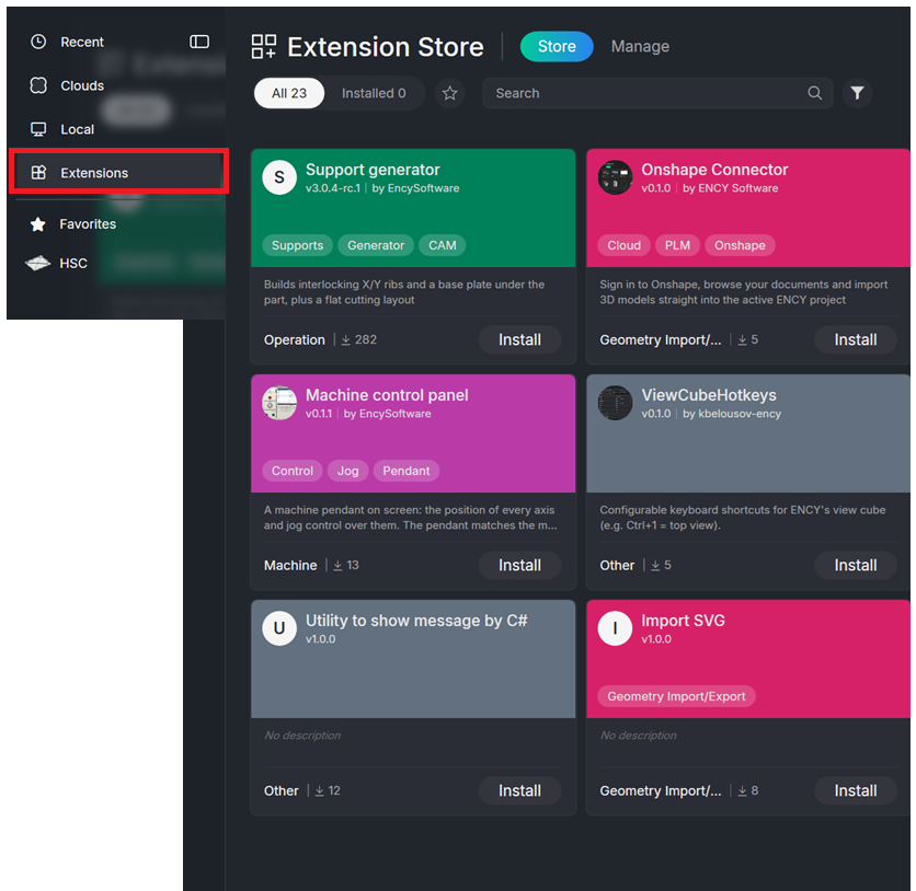
Extension Store.
The Extension Store is the place where optional add-ons for the CAM system are discovered, installed, updated, and removed. It connects a web catalog with the CAM application: the web storefront lists extensions and can start an installation, while the in-application tab performs the actual download, registration, and removal on the local machine. See more
The Extension Store is located on the Home page.
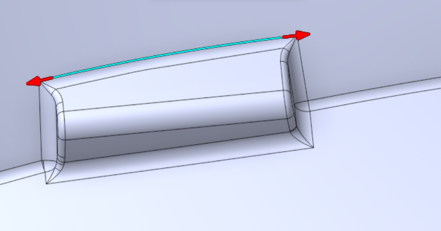
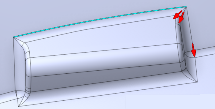
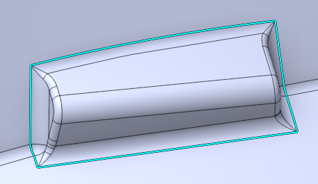
Added interactive fork steering for Loop edge selection - Custom Loop.
It lets the operator control, edge by edge, the direction the loop takes at every branch point (fork) it meets while propagating along the model, using the ◀ / ▶ keys. See more
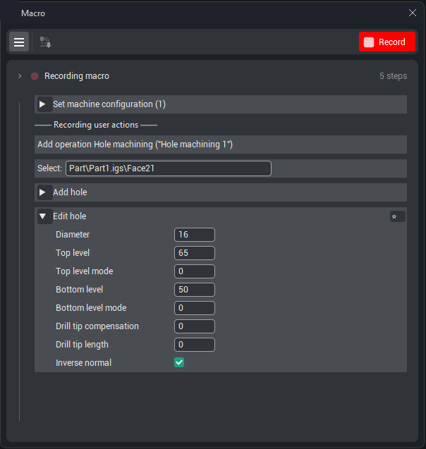
A new Macro option has been introduced.
It enables recording user actions, which can later be opened in VS Code. These macro can be saved and replayed as needed. See more
It is also possible to export all macro parameters to use them for working with another part, i.e., to simulate a standard technical process.
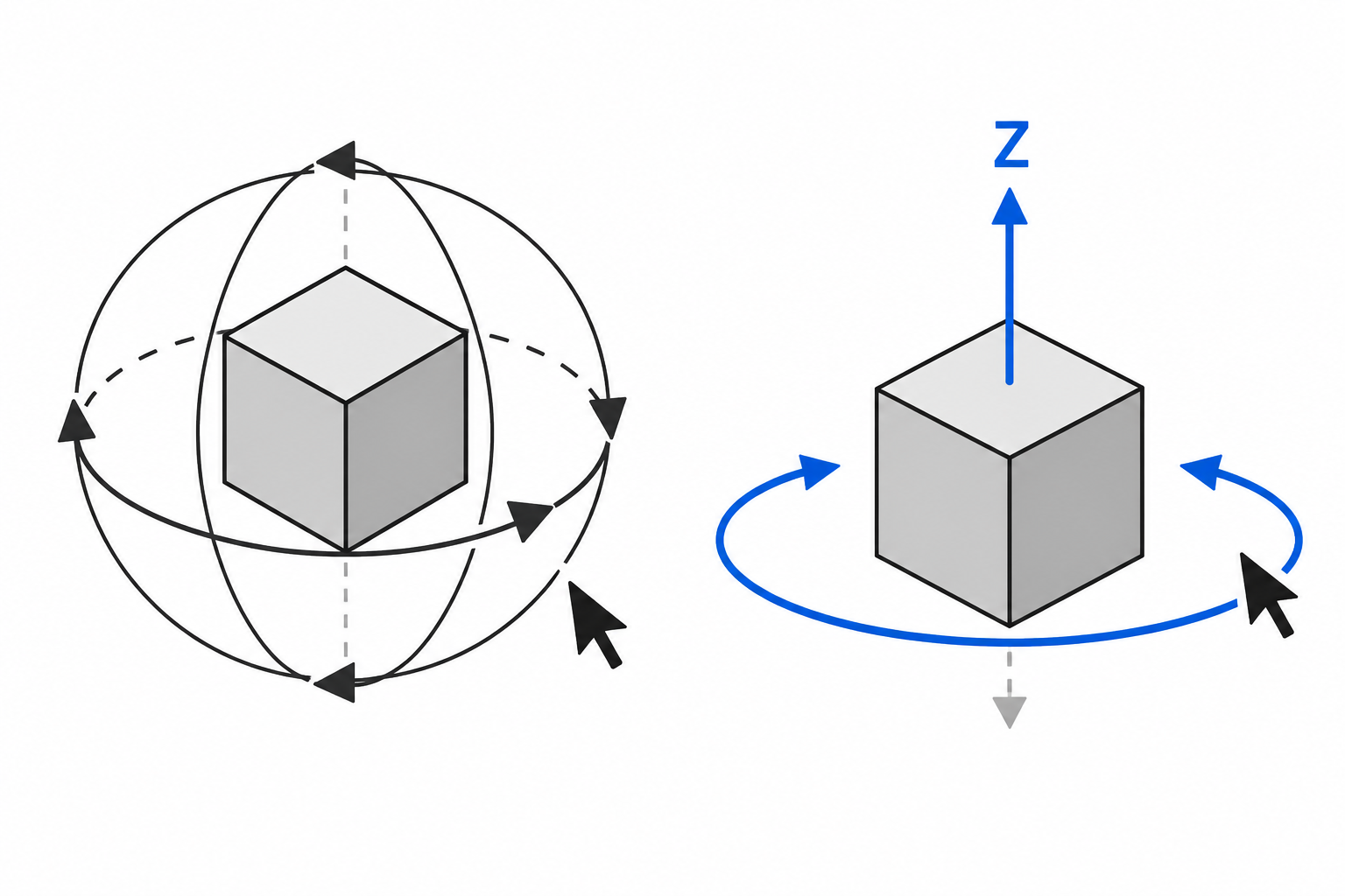
Added a new navigation mode for view rotation.
Rotation Mode — a new toolbar button that switches between free Trackball rotation and constrained Orbit rotation, in which a chosen local axis (X, Y or Z) is kept vertical on screen.
When Orbit mode is enabled, the view smoothly snaps so the selected axis becomes vertical, and horizontal mouse movement rotates the scene around it.
The button is located in the lower part of the screen on the View Control toolbar. See more