3D Tool Compensation

Application area:
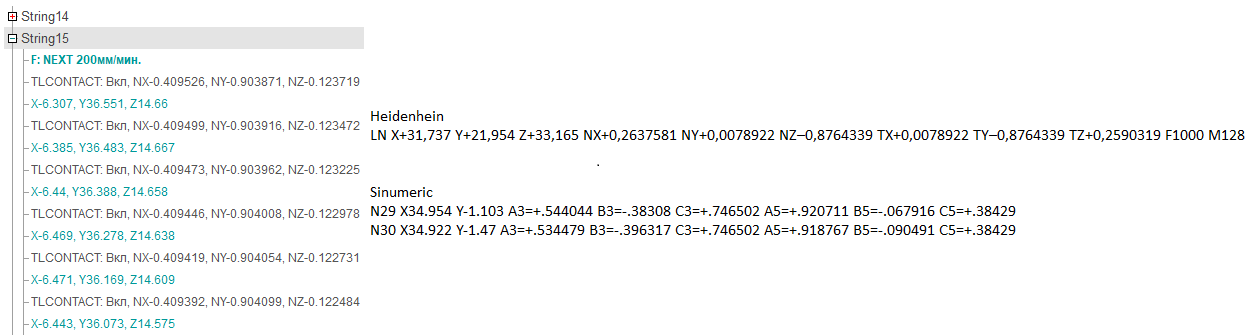
For surface finishing operations, the G‑code output may include the surface normal vector at the tool contact point. This enables the implementation of 3D tool compensation — a controlled displacement of the cutting tool relative to the workpiece surface at each point along the toolpath.
To include surface normal vector data in the G‑code output, enable the Set tool contact surface normal vectors (on Machine setup panel See more) flag in the machine schema settings. This generates a TLCONTACT (NX, NY, NZ) command in the CLData for each toolpath point. The postprocessor must then either:
output the contact normal directly to the G‑code frame, or
manually shift each path point along this vector by the specified correction amount, depending on the 3D compensation support of the target CNC system.