MachineMaker
  • MachineMaker
v3.1.1
Search Results for

    Show / Hide Table of Contents
    • MachineMaker
    • Introduction to MachineMaker
    • Interface
      • Main window
      • 3D navigation
      • Toolbar
      • Application Settings
    • Getting Started
      • Creating a project
      • Adding a mechanism
      • Prepare and import 3D objects
      • Grouping elements into nodes
      • Coloring
      • Mechanism Simulation and Validation
      • Assemblies
      • Mechanisms Library
      • Machine equipment configuration
    • Milling Machines
      • Building a kinematic scheme
      • Assembly options
      • Additional options
      • Examples: Machines
        • 3-Axes Milling Machine
        • 5-Axes Milling Machine
    • Robots
      • Building a kinematic scheme
        • Industrial Robots
        • Cobot
        • Heavy-Duty Robots
        • Flexible Heavy-Duty Robot
        • Tables and Positioners
        • Rails and Portals
        • Composite End effectors
      • Assembly Simulation and Validation
      • Table calibration
      • Receiving assemblies from CAM system
      • Assembly options
      • Additional options
      • Collision
      • Links/Leads
      • End effectors and TCP calibration
      • Examples: Robot cell
        • Simple robot
        • Heavy-Duty robot
        • Flexible Heavy-Duty Robot
        • Cobot
        • End Effectors
        • External Tools
        • Composite End Effector
        • Composite EndEffector: Spot Welding
        • Tables and User CS
        • Rail
        • H-bot (Portal)
        • SCARA Robot
        • Column-type robot
    • Turn-Milling Machines
      • Building a kinematic scheme
        • Chuck connector
        • Tool block
        • Turret head node
        • Dual-row tool turret
      • Multi Tool Head
      • Examples: Lathe milling machine
        • Lathe milling machine
        • Lathe milling machine with a dual-row turret
        • Swiss type machine
    • Simplifier

    Building a kinematic scheme

    Click Kinematictab to open kinematic parameters panel.Click_kinematic

    Kinematics

    MachineMaker shows the current mechanism's 3D model and kinematic scheme. It is necessary to build correct kinematic linkage by specifying connector's positions.

    The kinematic tree of mechanisms will be automatically built because of the pre-selected template on the "Model" tab. In cases if it will be necessary to make any changes in the mechanism tree the name of the template will change to "Custom".
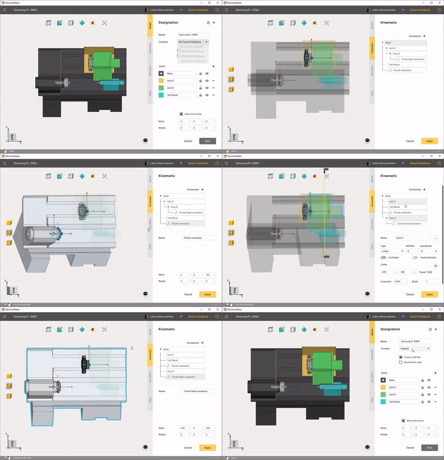
    шаблонкастомтокарка

    Since the appropriate template was originally selected, the only thing left to do is to position the Turret head connector and Chuck connector in the correct positions. Also set the limits for each node.

    Hold down the Left Ctrl key and drag the Turret head connector and Chuck connector to the desired position.
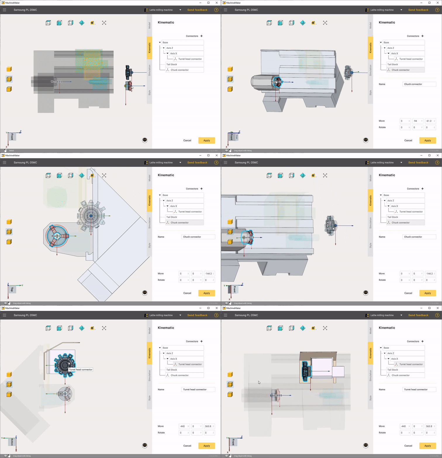
    кинематикатокарка

    Node limits on lathe milling machine can vary. We recommend that you set the original values for each node.
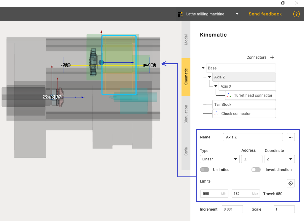
    image2024-4-24_11-14-42

    In this article
    Back to top MachineMaker