MachineMaker
  • MachineMaker
v3.1.1
Search Results for

    Show / Hide Table of Contents
    • MachineMaker
    • Introduction to MachineMaker
    • Interface
      • Main window
      • 3D navigation
      • Toolbar
      • Application Settings
    • Getting Started
      • Creating a project
      • Adding a mechanism
      • Prepare and import 3D objects
      • Grouping elements into nodes
      • Coloring
      • Mechanism Simulation and Validation
      • Assemblies
      • Mechanisms Library
      • Machine equipment configuration
    • Milling Machines
      • Building a kinematic scheme
      • Assembly options
      • Additional options
      • Examples: Machines
        • 3-Axes Milling Machine
        • 5-Axes Milling Machine
    • Robots
      • Building a kinematic scheme
        • Industrial Robots
        • Cobot
        • Heavy-Duty Robots
        • Flexible Heavy-Duty Robot
        • Tables and Positioners
        • Rails and Portals
        • Composite End effectors
      • Assembly Simulation and Validation
      • Table calibration
      • Receiving assemblies from CAM system
      • Assembly options
      • Additional options
      • Collision
      • Links/Leads
      • End effectors and TCP calibration
      • Examples: Robot cell
        • Simple robot
        • Heavy-Duty robot
        • Flexible Heavy-Duty Robot
        • Cobot
        • End Effectors
        • External Tools
        • Composite End Effector
        • Composite EndEffector: Spot Welding
        • Tables and User CS
        • Rail
        • H-bot (Portal)
        • SCARA Robot
        • Column-type robot
    • Turn-Milling Machines
      • Building a kinematic scheme
        • Chuck connector
        • Tool block
        • Turret head node
        • Dual-row tool turret
      • Multi Tool Head
      • Examples: Lathe milling machine
        • Lathe milling machine
        • Lathe milling machine with a dual-row turret
        • Swiss type machine
    • Simplifier

    Additional options

    Robot controller can use external axes and it is necessary to assign correct positions (indices) for these axes in the assembly. Default CAM-system postprocessors use index-based axes identifiers (ExtAxis1Pos for the first axis, ExtAxis2Pos etc). Some custom postprocessors can use axis address instead of indices (E1, E2, E3, J4 etc).

    Click Additional options button to open the Assembly parameters panel. Then go to the Axes tab.
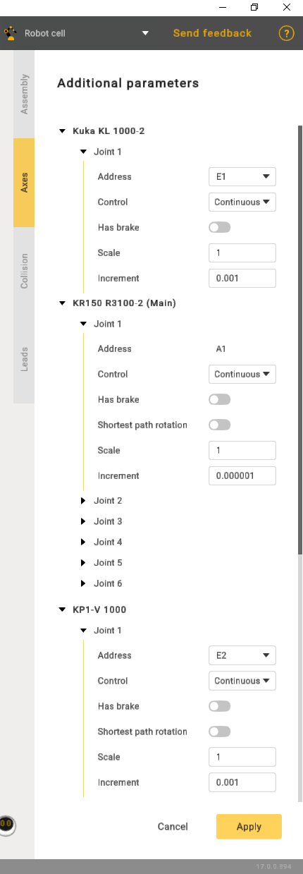
    Additional options

    • Address - axis designation.
    • Control:
    1. Countinuous.
    2. Indexed - indicates that rotation will be carried out incrementally.
    3. Manual - implies that the operation is entirely manual.
    • Shortest path rotation - refers to the rotation around an axis or point using the most direct path between the initial and final positions in three-dimensional space.
    • Scale is a setting with four positions. Each position corresponds to a specific angular increment. Position 1 equals 90 degrees, Position 2 equals 180 degrees, and so on.

    Define Address and External axis position (index) here. MachineMaker will show axis identifier (like ExtAxis3Pos) in tooltip. You can use it in the postprocessor.
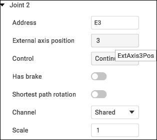
    Additional options

    Axis address and axis index must be unique in the assembly context. If you try to set use a value that has been already taken, MachineMaker will propose to replace the existing one.

    It is not possible to change the robot axis address and index. You can change external addresses only.

    It is also possible to define additional axes parameters here: Control type (Continues, Indexed, Manual), Brakes and Shortest path rotation mode.

    In this article
    Back to top MachineMaker