MachineMaker
  • MachineMaker
v3.1.1
Search Results for

    Show / Hide Table of Contents
    • MachineMaker
    • Introduction to MachineMaker
    • Interface
      • Main window
      • 3D navigation
      • Toolbar
      • Application Settings
    • Getting Started
      • Creating a project
      • Adding a mechanism
      • Prepare and import 3D objects
      • Grouping elements into nodes
      • Coloring
      • Mechanism Simulation and Validation
      • Assemblies
      • Mechanisms Library
      • Machine equipment configuration
    • Milling Machines
      • Building a kinematic scheme
      • Assembly options
      • Additional options
      • Examples: Machines
        • 3-Axes Milling Machine
        • 5-Axes Milling Machine
    • Robots
      • Building a kinematic scheme
        • Industrial Robots
        • Cobot
        • Heavy-Duty Robots
        • Flexible Heavy-Duty Robot
        • Tables and Positioners
        • Rails and Portals
        • Composite End effectors
      • Assembly Simulation and Validation
      • Table calibration
      • Receiving assemblies from CAM system
      • Assembly options
      • Additional options
      • Collision
      • Links/Leads
      • End effectors and TCP calibration
      • Examples: Robot cell
        • Simple robot
        • Heavy-Duty robot
        • Flexible Heavy-Duty Robot
        • Cobot
        • End Effectors
        • External Tools
        • Composite End Effector
        • Composite EndEffector: Spot Welding
        • Tables and User CS
        • Rail
        • H-bot (Portal)
        • SCARA Robot
        • Column-type robot
    • Turn-Milling Machines
      • Building a kinematic scheme
        • Chuck connector
        • Tool block
        • Turret head node
        • Dual-row tool turret
      • Multi Tool Head
      • Examples: Lathe milling machine
        • Lathe milling machine
        • Lathe milling machine with a dual-row turret
        • Swiss type machine
    • Simplifier

    Assembly options

    Click Assembly options button to open Assembly parameters panel.
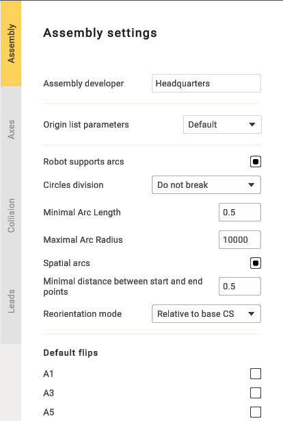
    Assembly options

    • Snap base to rotary positioner: When enabled, this option attaches the coordinate system to the rotary positioner, moving with it. When disabled, the coordinate system on the positioner remains stationary.
    • Snap base to linear axis: Functions similarly to "Snap Base to Rotary Positioner," but is used with linear axes.
    • Fix WCS on axis: This option is used to select the axis of the coordinate system. For example, if you have multiple mechanisms and need to choose a specific one.
    • Assembly developer: Company name.
    • Robot supports arcs: Necessary to output arcs in the control program.
    • Circles division: Used to divide arcs into halves or quarters.
    • Minimal Arc Length: Prevents the output of arcs shorter than a specified length; a segment will be displayed instead.
    • Maximal Arc Radius: Prevents the output of arcs with a radius larger than specified; segments will be displayed.
    • Spatial arcs: Arbitrary spatial arcs. A function necessary for robots to work.
    • Minimal distance between btart and end points: A restriction that allows the display of segments with a small distance between points.
    • Reorientation mode: The method of calculating the midpoint. The functionality may vary depending on the manufacturer.
    • Default flips: Needed to set the position of the robot.
    In this article
    Back to top MachineMaker