Highlights in ENCY
Additive manufacturing updates
-
General improvements
Interface
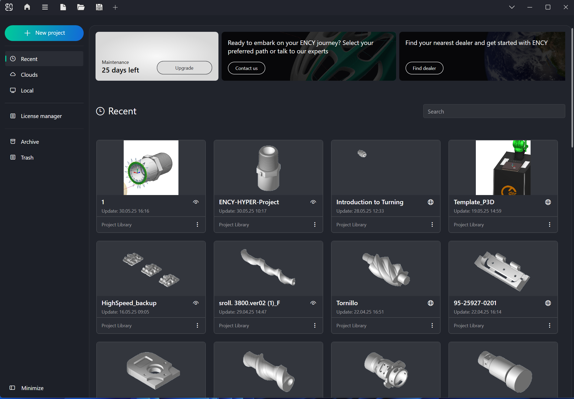
Added a Home Page.
Added a Home Page that includes lessons for mastering the system, a library of projects and the latest news about the system and others. See more
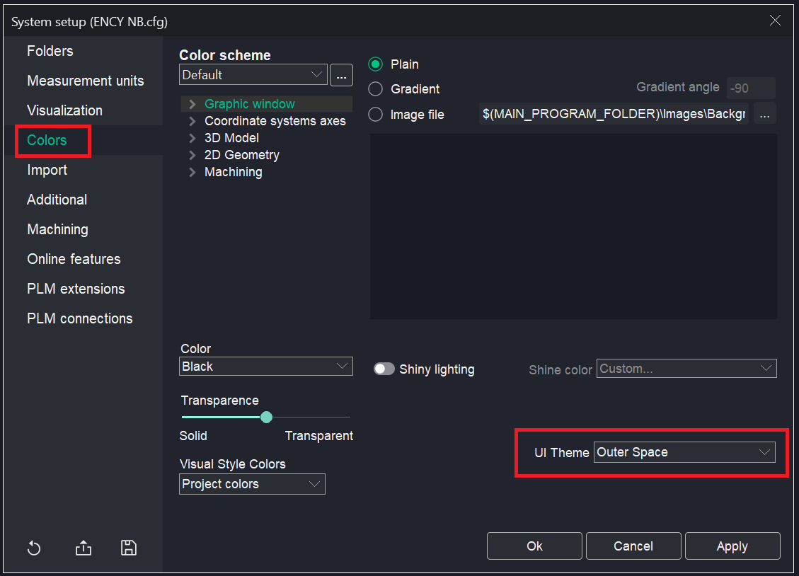
Added UI theme.
Three themes are available.
Outer Space - Charcoal - Bright Gray- Gray.
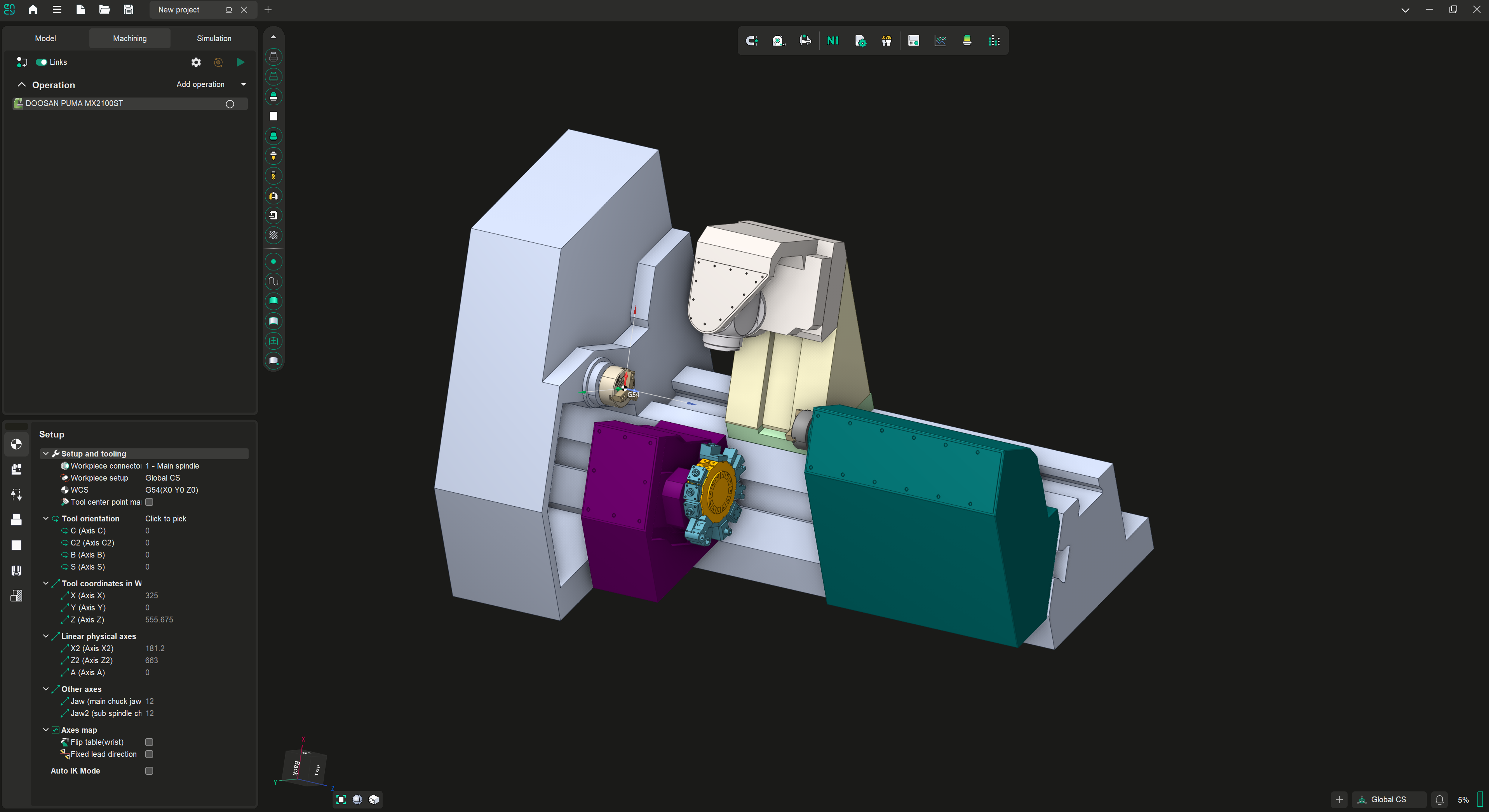
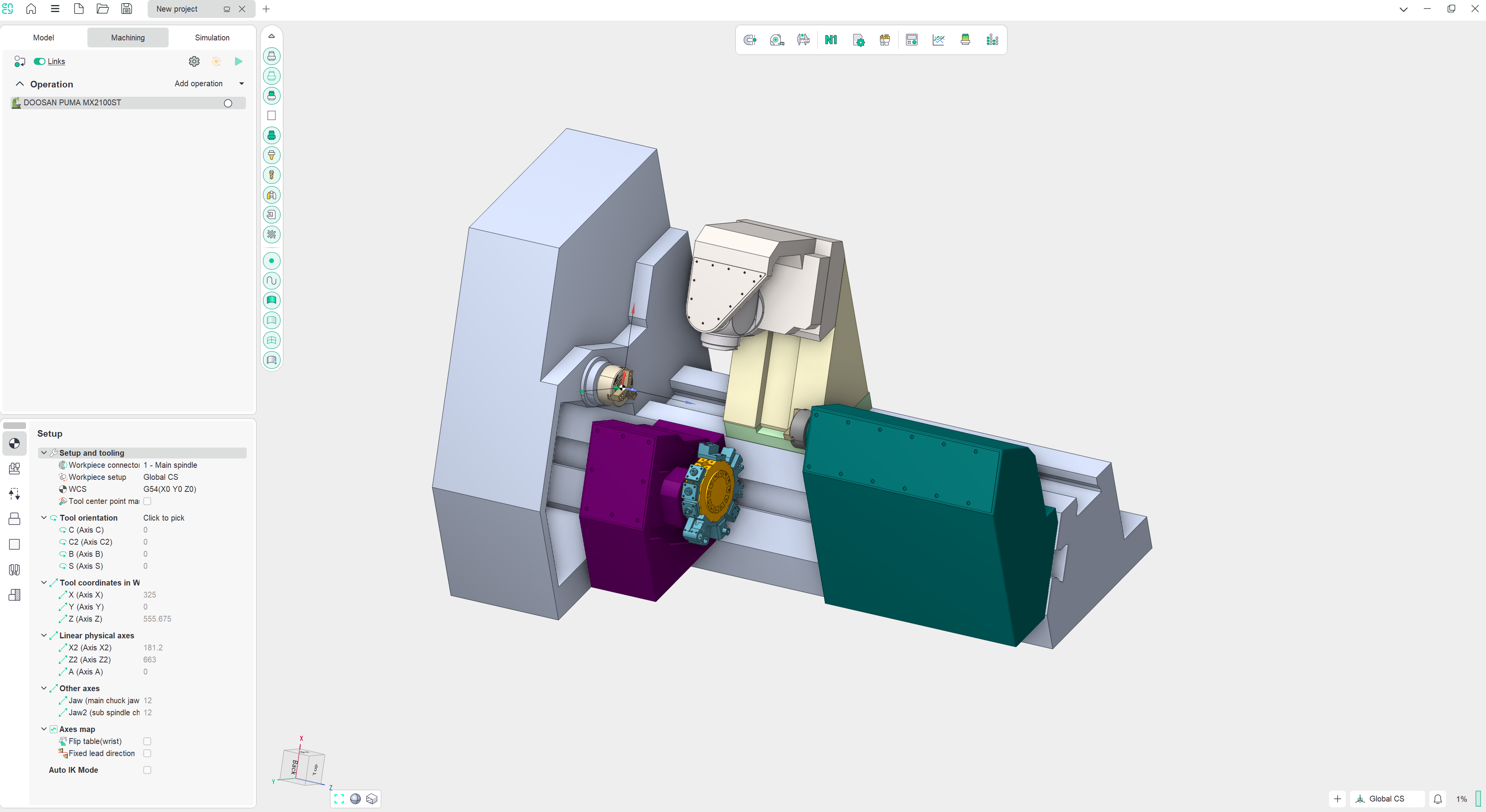
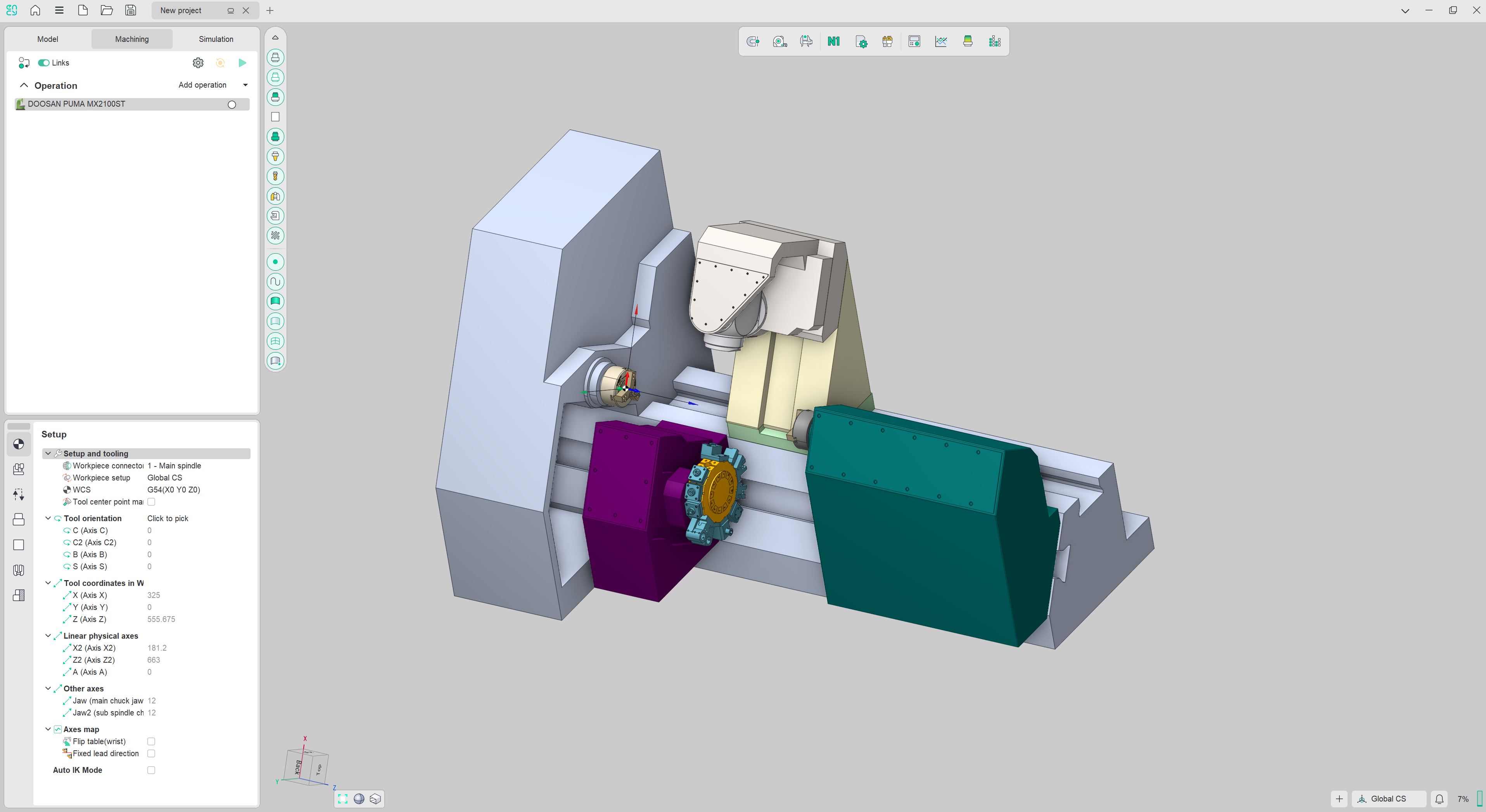
To change the theme you need to go to System setup - Colors - UI Theme.
The CAM system now launches faster.
Work has been performed to optimize the system’s startup performance. The main window now opens considerably faster as a result.
Technology updates
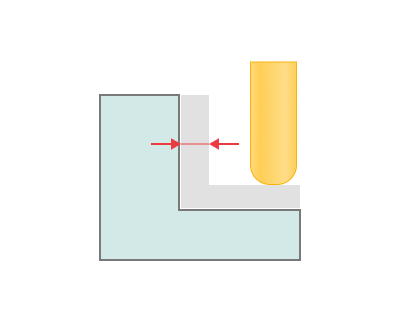
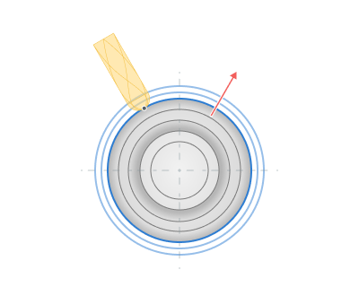
Added the "Corner control" parameter group.
This feature allows you to control the feed in the corners of the toolpath. It's now available for "Contouring", "Additive", "Spraying" and other operations. See more.
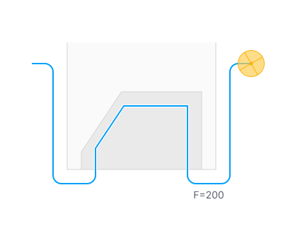
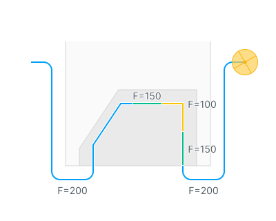
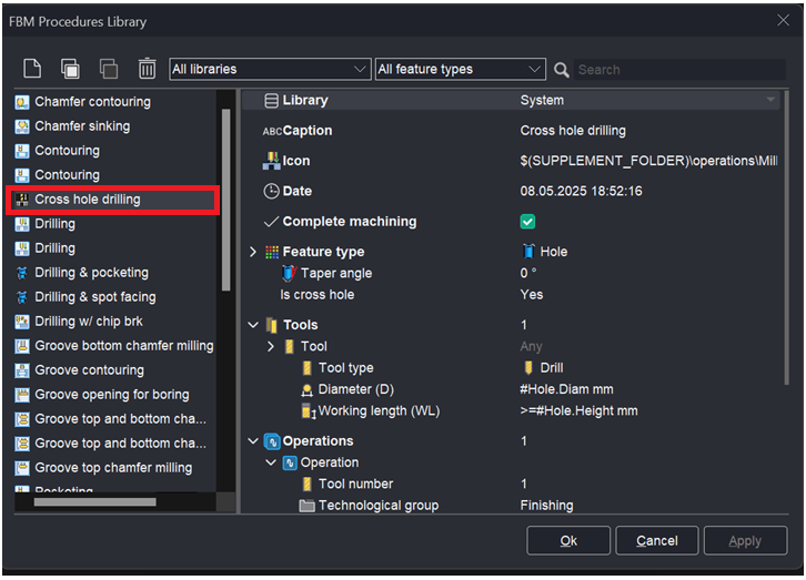
Added Optimize Feed in Cross Holes Option.
The Optimize Feed in Cross Holes option has been added for the drilling operation (works only with NC Code Format - Long Hand). See more .
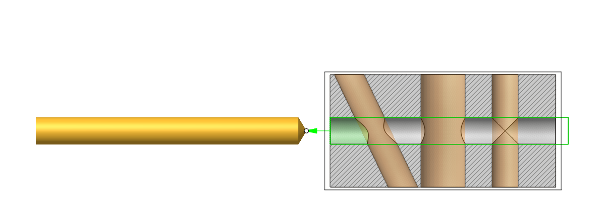
This technology is also available in FBM (See more). Rules have been created for simple drilling. You can also add your own rules for writing processing.
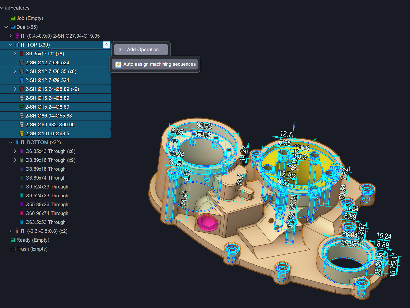
The FBM operation has been significantly improved.
The ability to automatically assign processing rules to a group of holes in a specific plane has been added (Auto assign machining sequences). See more
Pocketing and hole (stepped) operations have been improved.
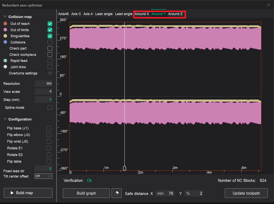
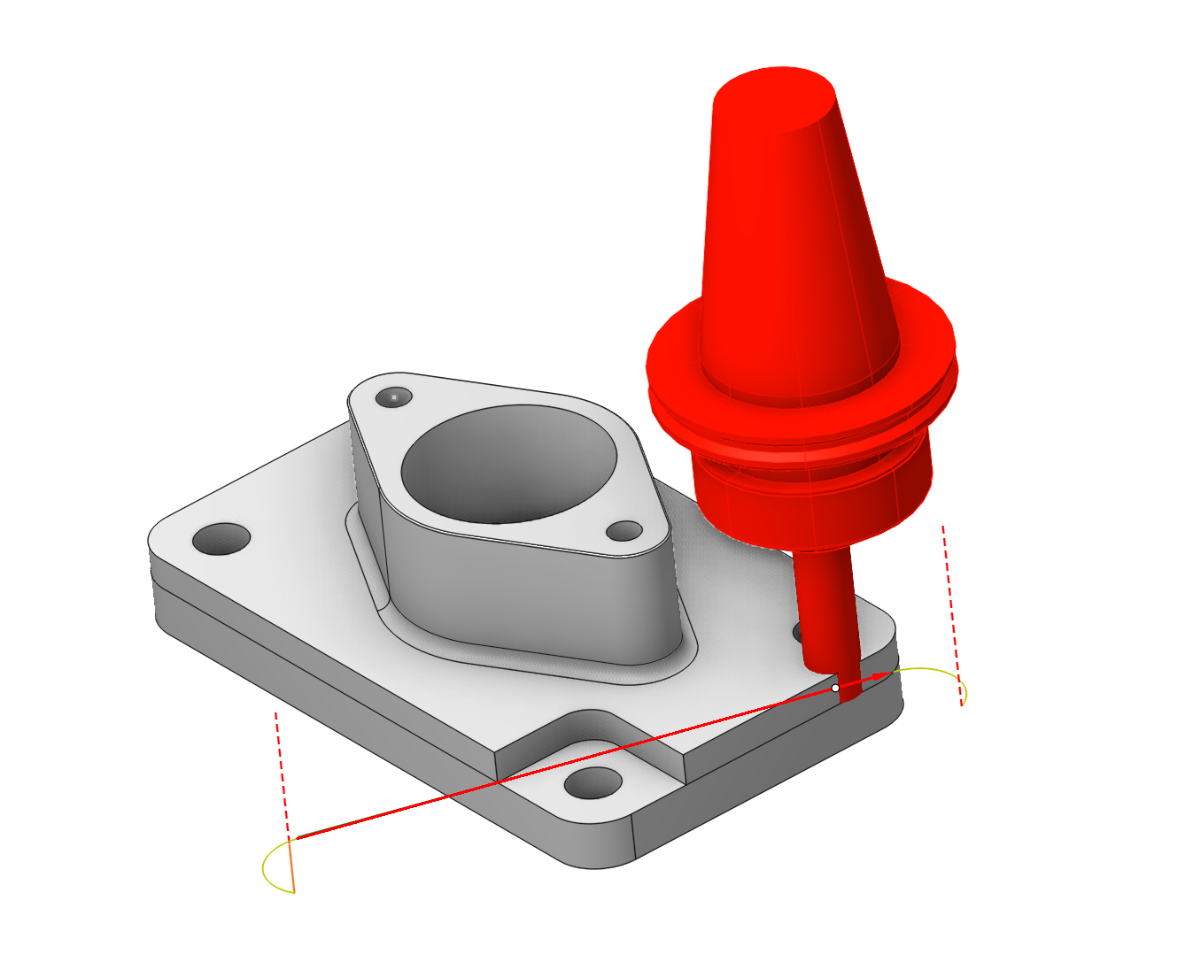
Added rotate toolpath by LocalCS in Robot Map feature
Added new rotation maps relative to a fixed coordinate system. See more
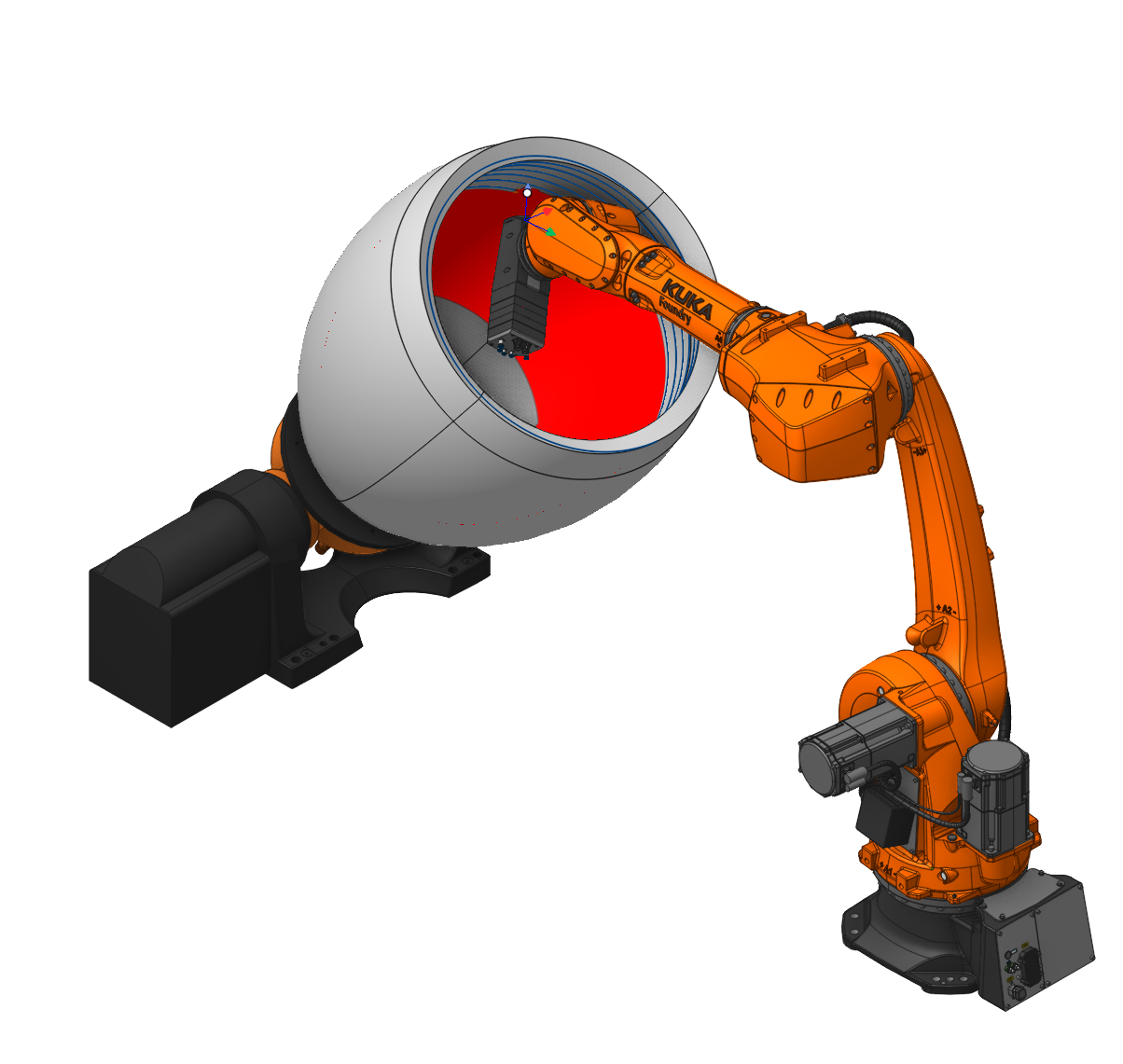
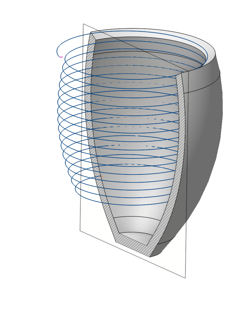
Added new parameter Machining from inside
The parameter allows processing of the internal surfaces of the part. In the section Job zone. See more
Available in operations:
Rotary finishing (Rotary spraying)
Morph (Morph spraying)
6D Contouring (Contour spraying)
5D Surfacing (Surface spraying)
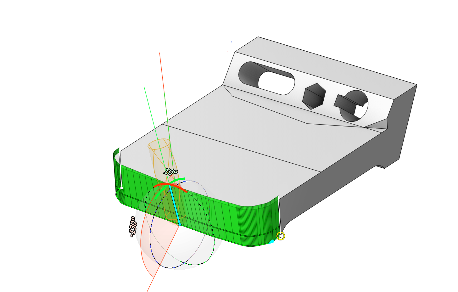
Added new parameter for 6th axis control - Fixed Lead Direction.
It fixes the movement of the tool at the selected angle in the map (Lean angle, Lead angle) relative to the selected global coordinate system. See more
Added new parameter for Check Holder - Fixed tilting direction.
Works similarly to the parameter Fixed Lead Direction. It differs in that the Lean angle and Lead angle are regulated by the gaps specified in the Check Holder parameters. See more
Improvements in 5D curve interaction
Added vector rotation on two axes and enhanced multi-select functionality. See more
Added interactive elements
Interactive elements for the operations 5D Surfacing, Morph, 6D Contouring and Scallop have been added to the parameters Rotary axis, Side angle, and End side angle.
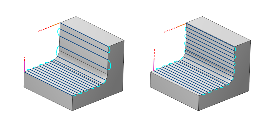
Improvement in the Swarf operation.
Performance with Barrel tools in Swarf operations has been optimized.
Swarf has expanded its capabilities by adding support for barrel tools. See more
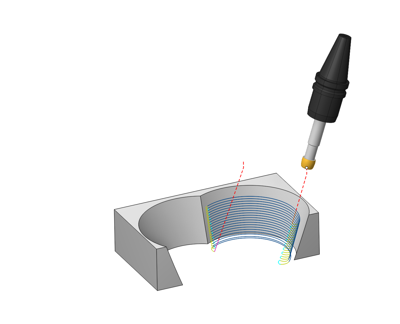
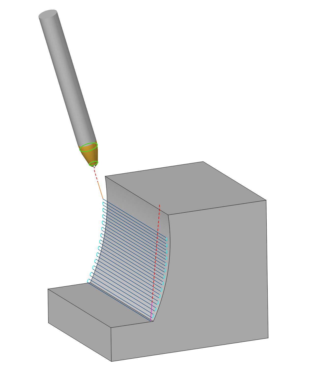
Contact Points.
The contact points function allows to set two points of contact between the tool and the surface. Each vertical pass gradually changes the tilt of the tool from the start param to the end param. See more
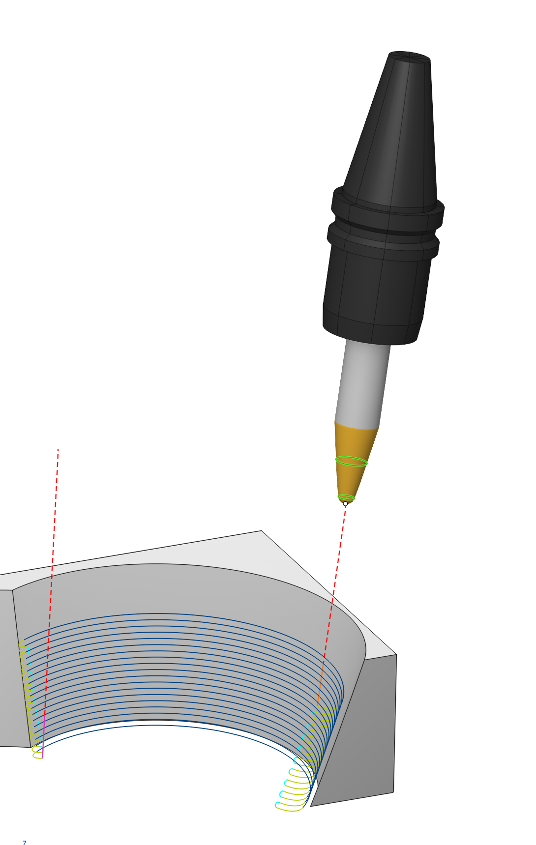
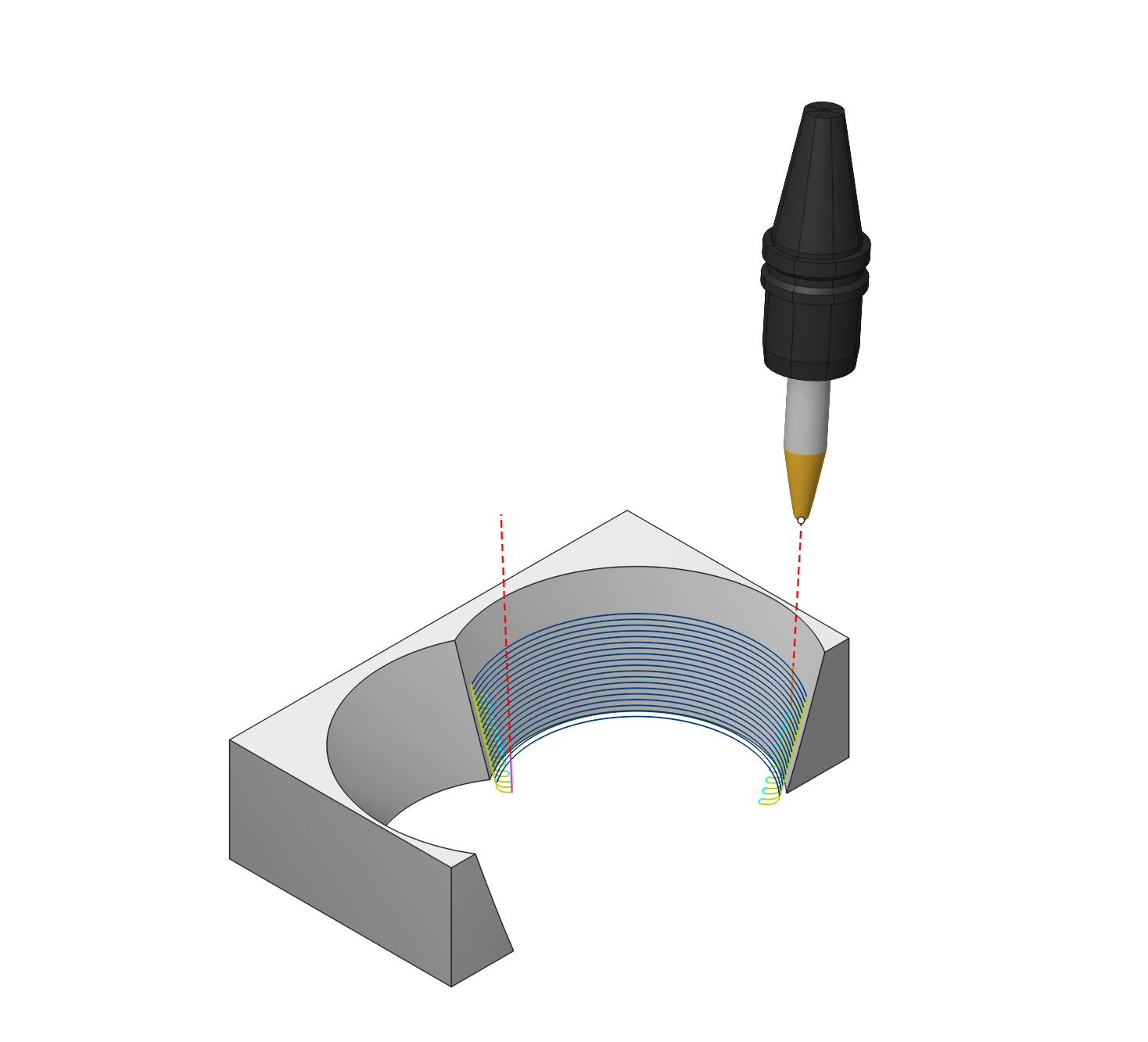
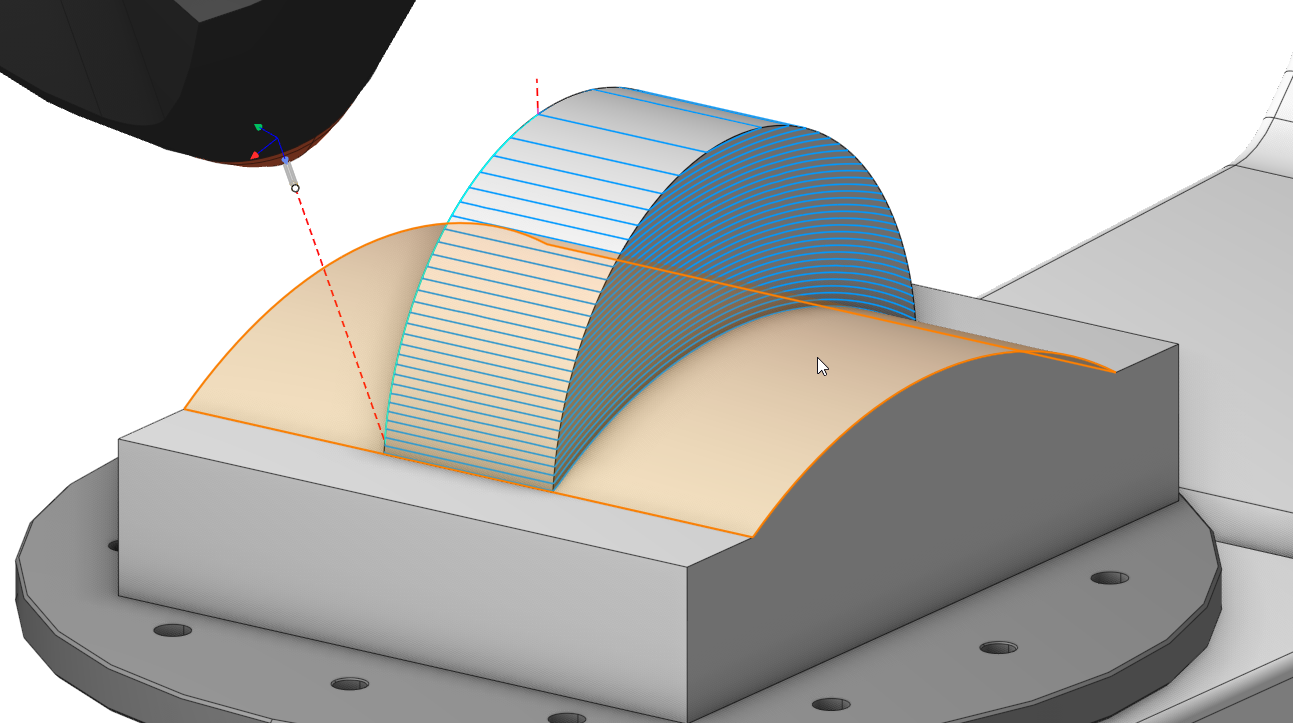
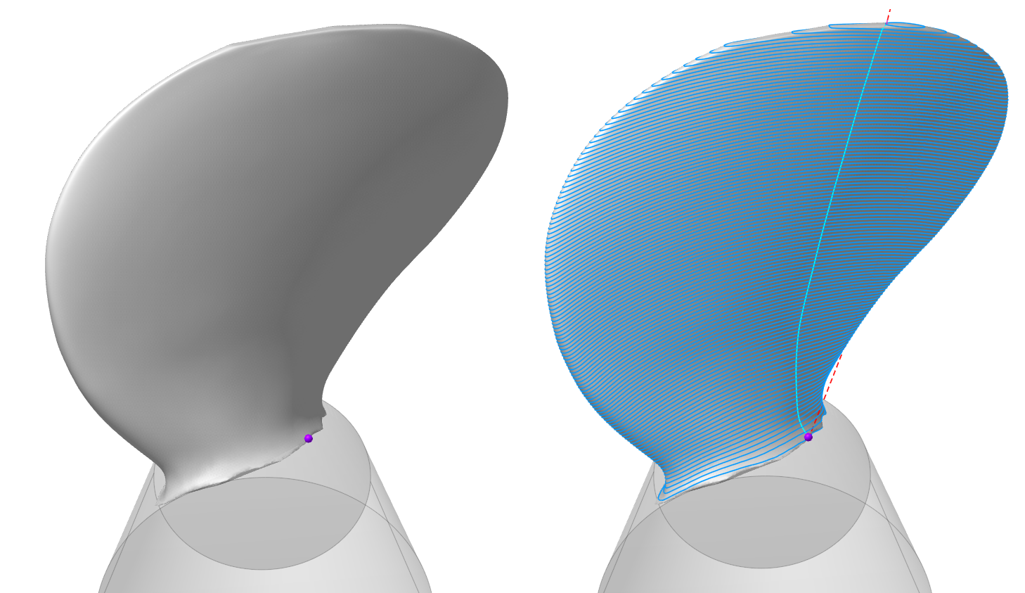
Improvement in the 5D Surfacing operation.
Contact Points.
The operation now has the ability to uniformly change the tool's contact point from the initial line to the final line. Suitable for tools of the type Taper barrel mill. Available for operation 5D Surfacing. (located in the Tool Orientation group) See more
Adpative step.
In the 5D Surfacing operation, the adaptive step for the 'parallel to curve' strategy has been improved. Now the passes are generated with a uniform step when the adaptive step is enabled.
The Project Toolpath onto the Part option has been updated.
A new By surface normal option has been added. See more
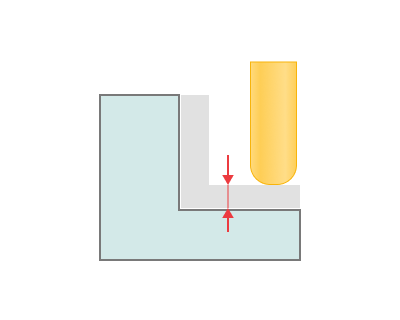
Radial/Axial stock.
For the 5D Surfacing operation, the stock allowance has been separated into axial and radial.
 The "Project Toolpath onto the Part" oion has been updated
o the Part" option has been updated.
The "Project Toolpath onto the Part" oion has been updated
o the Part" option has been updated.
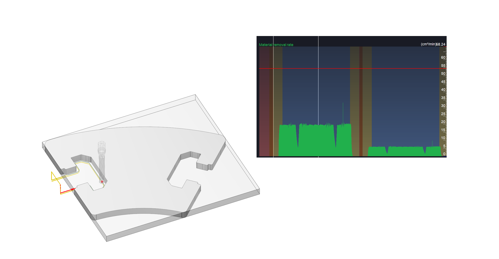
Added a new option to Graph of the axes - Graph of the volume of material removed.
By analyzing the Graph of the volume of material removed for different machining parameter settings (e.g., different cutting speeds, feed rates, depths of cut), the optimal parameters that maximize material removal rate while maintaining desired part quality can be identified.
Added an option to enable machine collision detection during background machining result calculation.
The algorithm background machining result calculation has been reworked. See more
The result of background machining result allows you to control after calculate:
tool collision with model
collision of the holder with the model
machine collision with model
Direct editing of the Collisions Ignore List is now supported within the CAM system.
Implemented direct editing of the CDIgnoreList section in the machine scheme directly from CAM system. Previously, editing required manual data entry in Notepad or the use of MachineMaker.
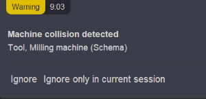
When a collision occurs during simulation, a notification appears indicating that a collision between nodes has occurred. A Ignore or Ignore only in curent session button has been added to this notification. See more
Added a new collision avoidance algorithm
The collision avoidance algorithm was enhanced by removing the safe distance requirement in the minimum-distance calculation, significantly improving computational efficiency.
Added an automatic robot axis map
We've introduced an intelligent robot axis mapping tool that simplifies trajectory planning for complex multi-axis systems (including rotary tables and linear axes with DoF >6). Unlike traditional robot axis map, our new solution automatically generates collision-free, singularity-avoiding trajectories while maintaining all movements within safe axis ranges - delivering optimal path quality with minimal user effort.
Additive manufacturing updates
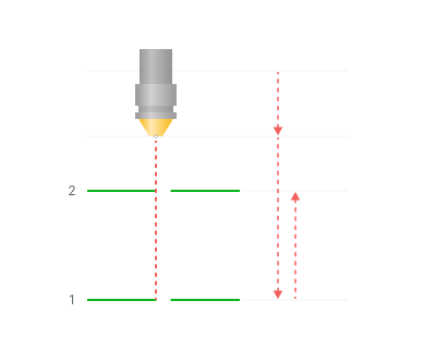
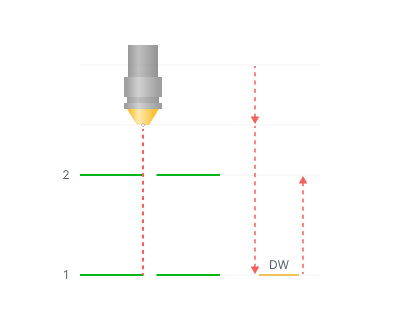
Minimum layer time parameter
New technology parameter has been added to all of our additive operations. It allows you to set the minimum allowed time in seconds for printing a single layer. Also some additional parameters available. See more.
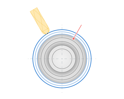
Passes order for Rough passes in Rotary finishing
For additive processing, sorting was added for starting from the outer contour or from the outer. See more
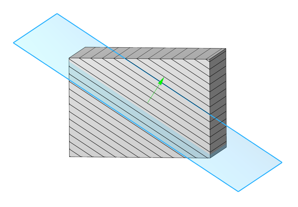
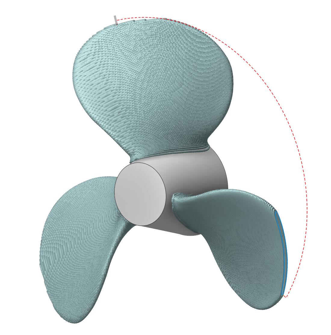
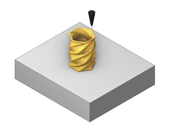
Improvings in Non-planar slicing operation
Surfaces support
Now "Non-planar slicing" operation can operate with model surfaces also. You can load your IGES, STEP and similar models and use them to create a non-planar additive toolpath. See more
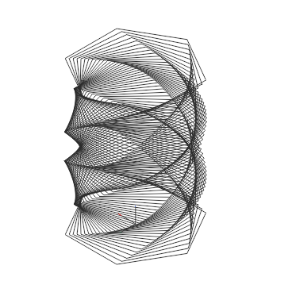
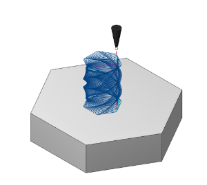
Planar slicing strategy
Added new planar strategy to the "Non-planar slicing" operation, which allows you to use the power of non-planar slicer with planar slices.
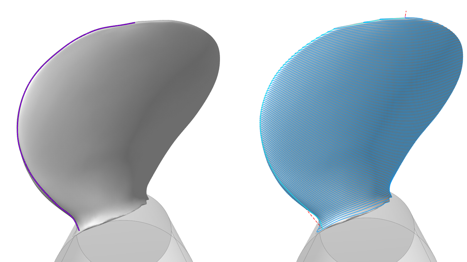
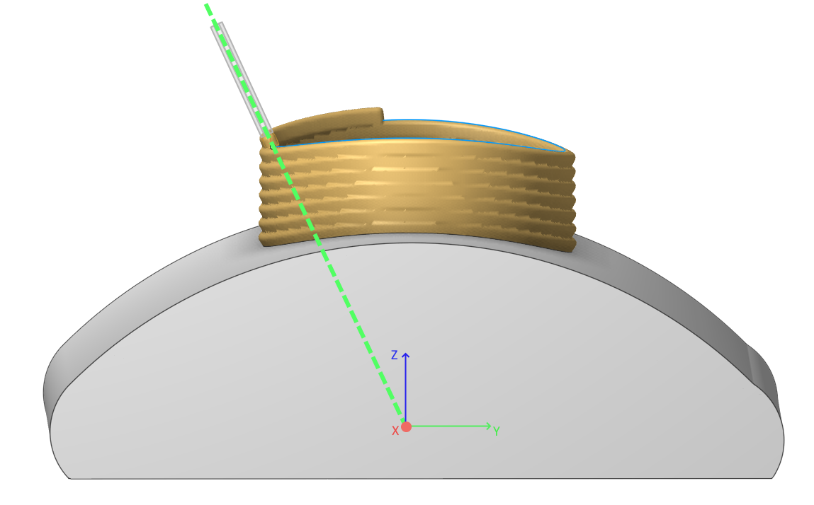
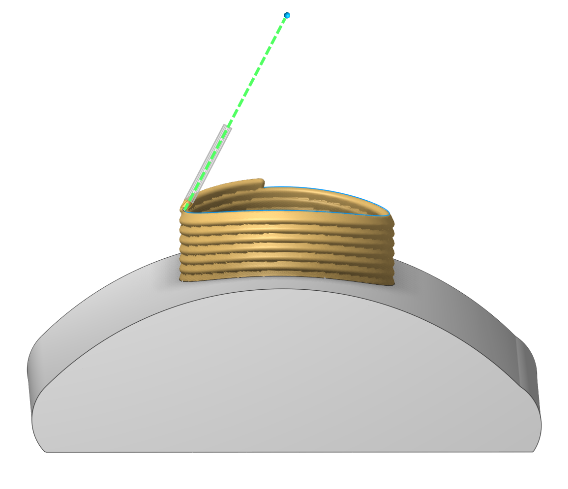
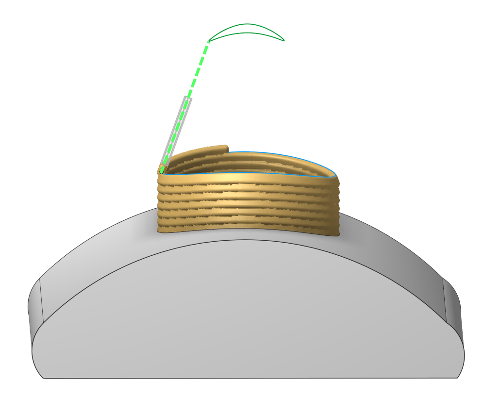
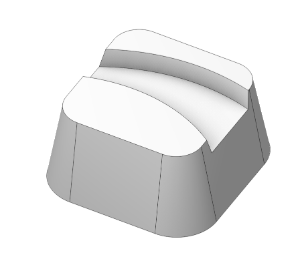
Deciding starting point
Now it's possible to set custom rules for deciding starting point on print layers. It's available to choose start point for the first layer only, or you can choose the curve for deciding starting points for all layers. See more
|
|
|
|
Start point |
Connection curve |
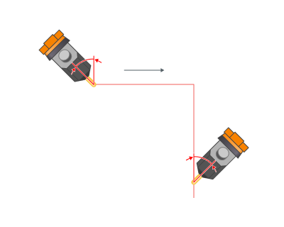
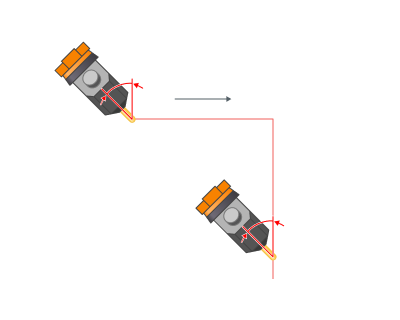
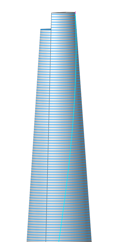
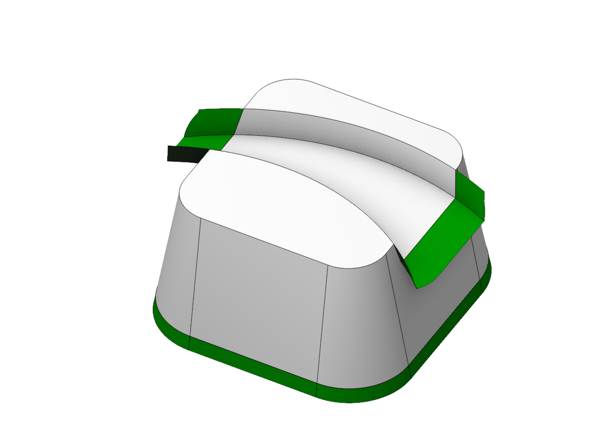
Start point shift
The start point shift relative to the previous layer allows to get a more even distribution of zones where the feed of material starts/stops and where the quality of the formed surface is usually lower. See more
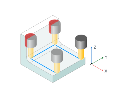
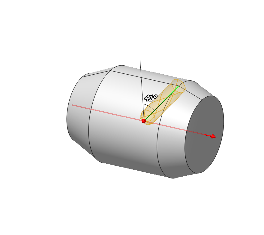
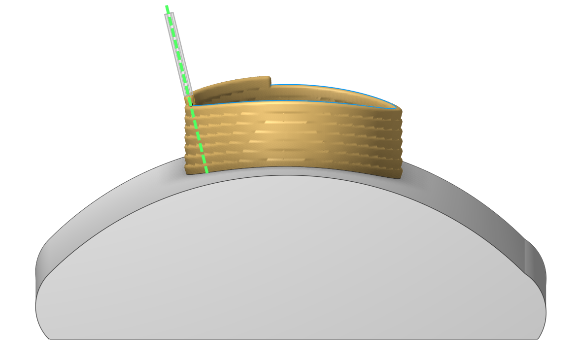
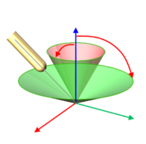
Tool orientation parameter
The "Tool orientation" parameter, which you can know from such operations like "5D Surfacing" or "Cladding 5D", has been added now to the "Non-planar slicing" operation also. There are five options avalaible for users: "Normal to surface", "Fixed", "To rotary axis", "Through point" and "Through curve". See more
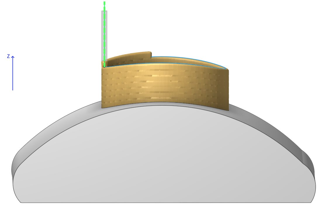
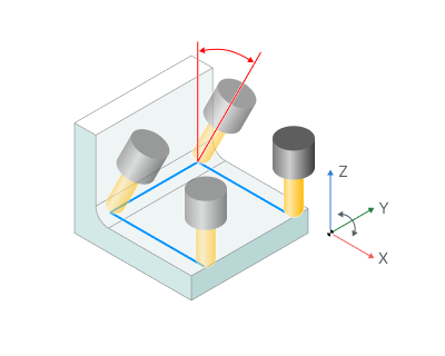
Limit rotation angles parameter
The "Limit rotation angles" parameter well known from "5D Surfacing" or "Cladding 5D" operations has also been added to the "Non-planar slicing" operation. See more.
Multi-feature support, sorting parameters and multiplying
The "Non-planar slicing" now supports printing multiple features on a single substrate. You can add these features individually on the Job assignment page or duplicate them using the multiplying parameters.
To give you better control over the printing process, we’ve also added new sorting parameters. You can choose to print: layer by layer, feature by feature or split the printing process every N layers using a new parameter. See more
Infill updates
Now it's possible to set a custom normal vector and rotation angle for infill orientation.
And we've also added new infill pattern types. See more
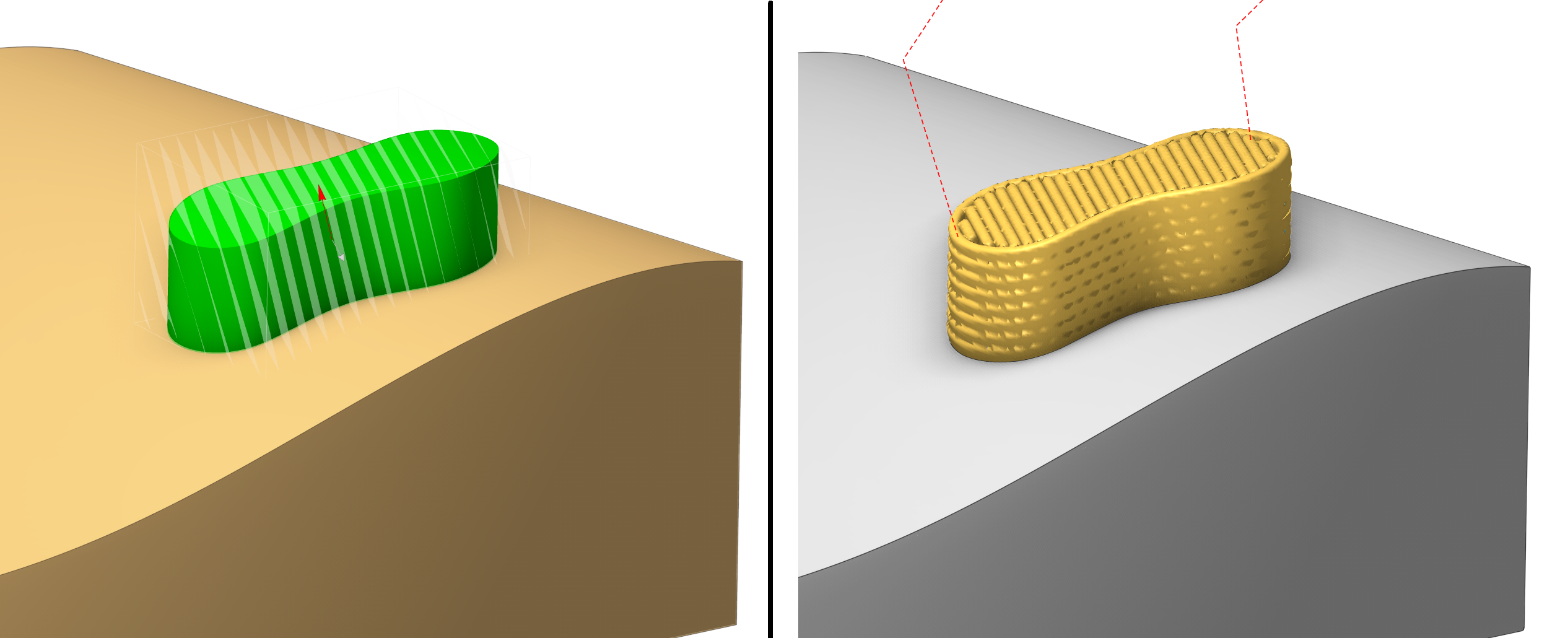
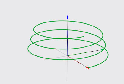
Added a new Direct cladding operation
The operation lets you do surfacing along curves you’ve set up beforehand. You can prepare the curves using any tool — for example, a third‑party CAD program. Basically, the operation turns a bunch of curves into a path for the tool to follow. It also automatically sorts and divides the work area into regions. You can choose between layer‑by‑layer and spiral processing modes. See more
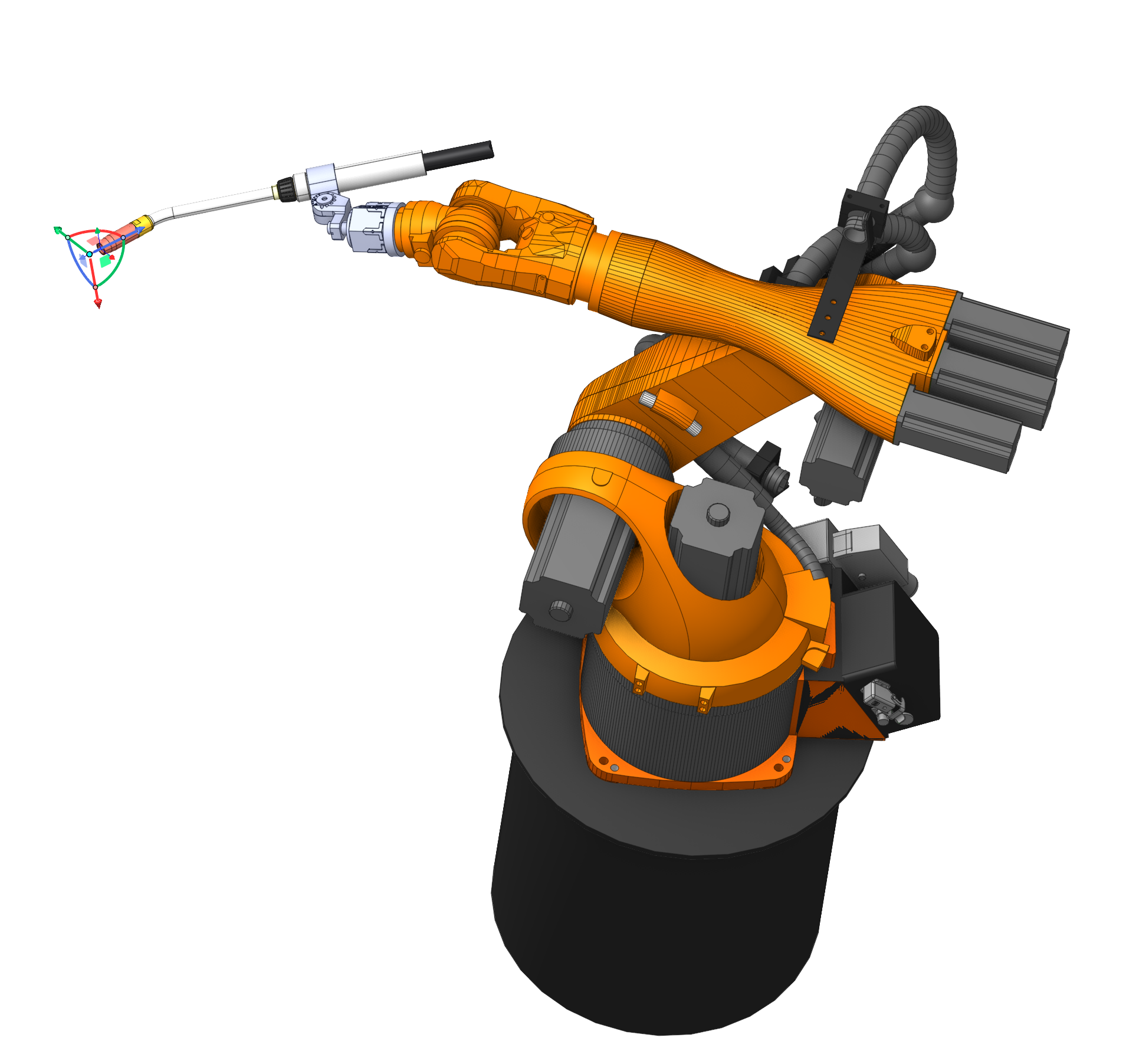
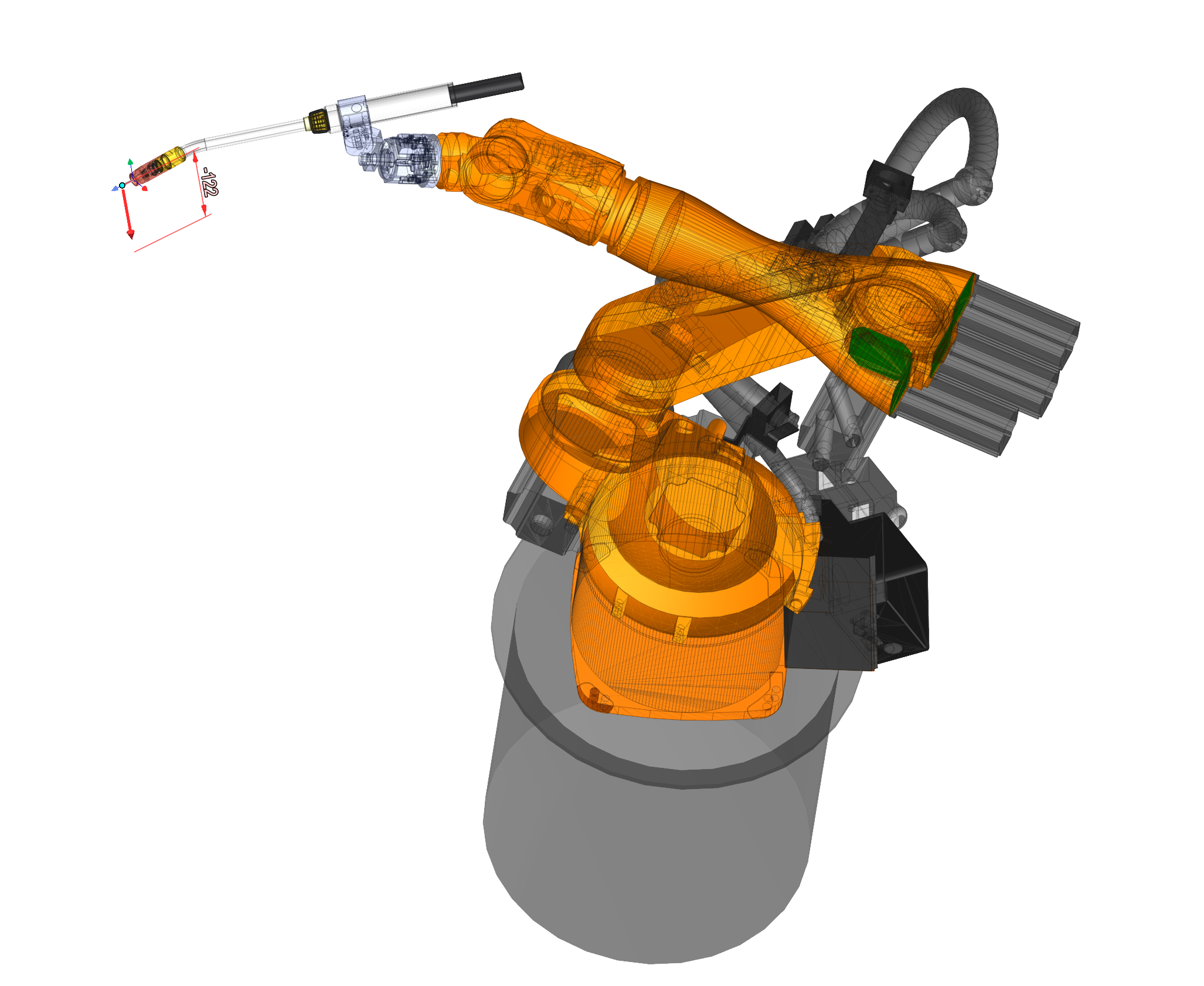
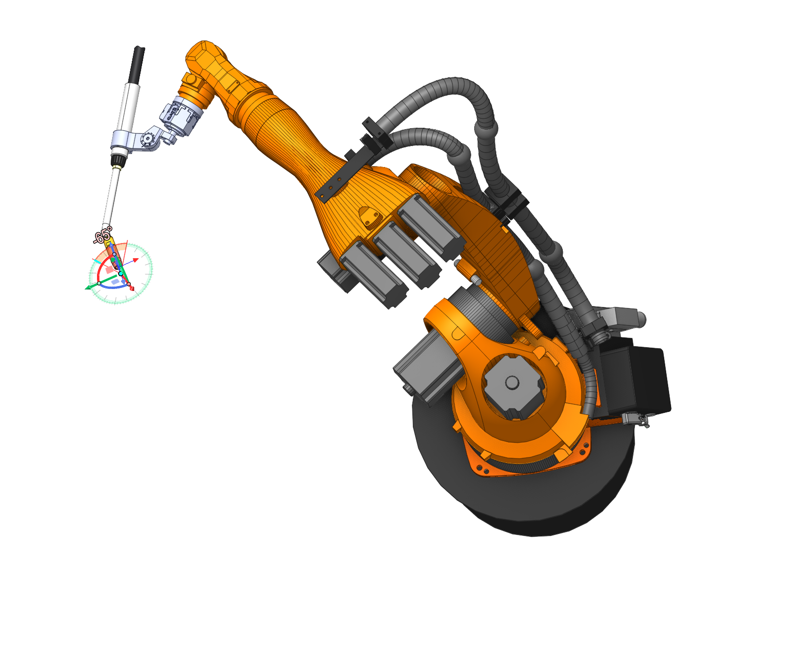
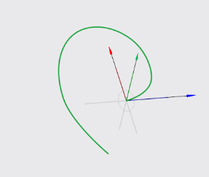
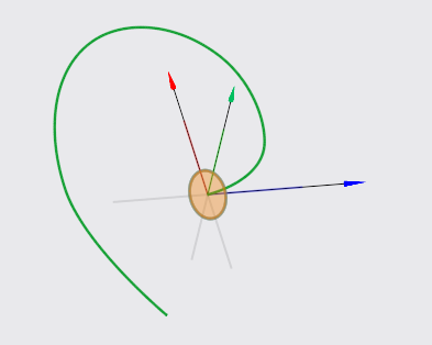
Gimbals have been added
Gimbals have been added as a visual tool for manipulating (moving, rotating) objects in 3D space. They provide an interactive way to precisely control the position and orientation of objects.
Gimbals have been added for use in the following cases:
Robot TCP movements
Defining 6th axis control via custom point
Defining a point when controlling the tool axis via point
Tool axis orientation
Fixture placement
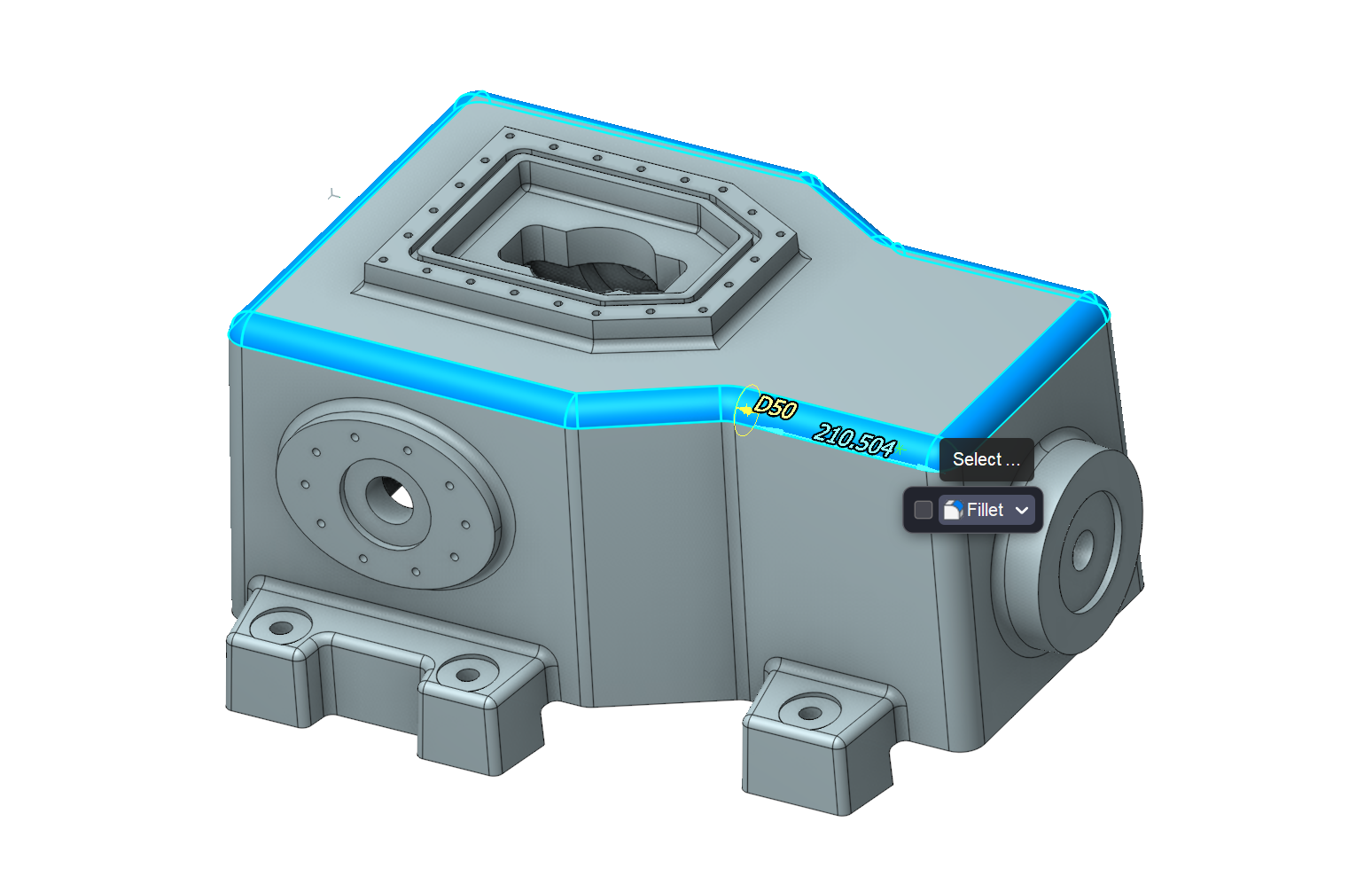
Update on working with the model
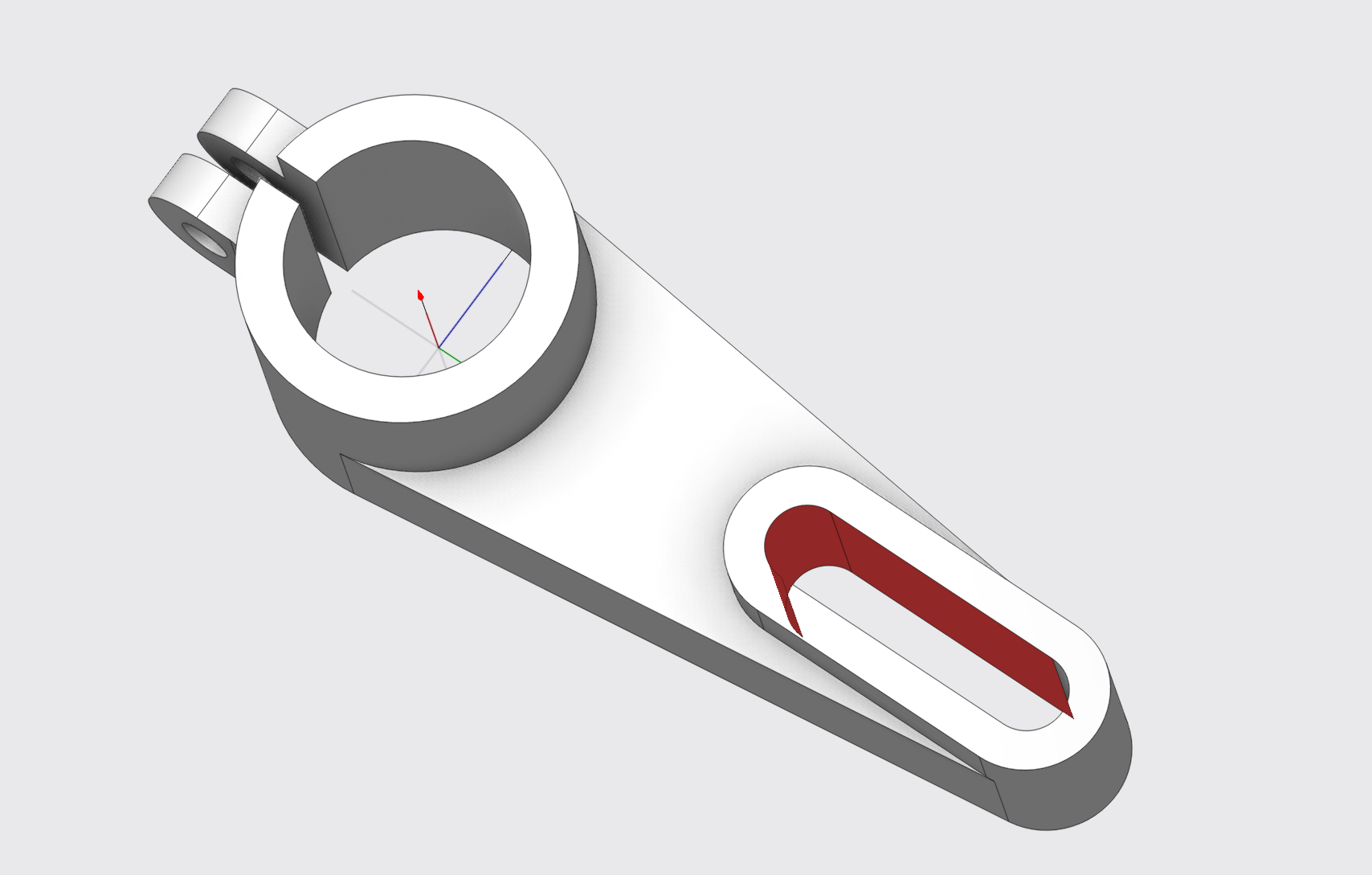
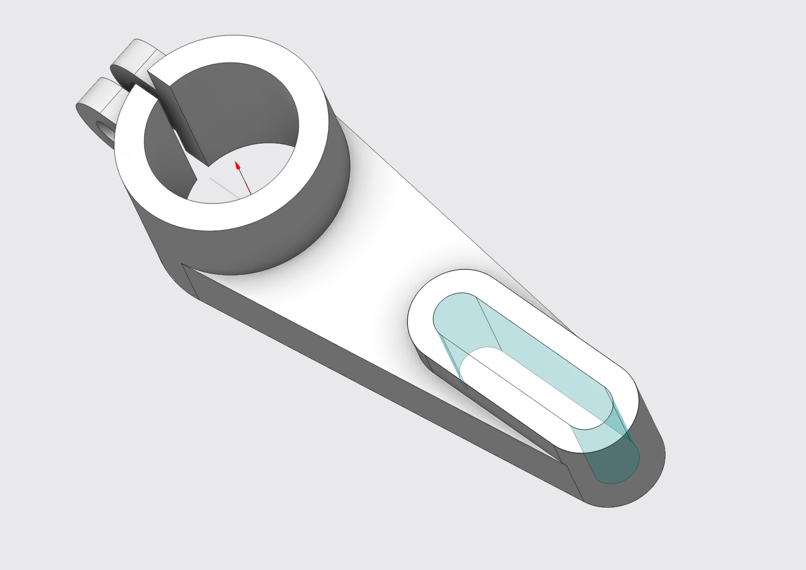
Extend surface option has been added
We added the Geometry Extension option in Model mode. The technology previously introduced in the work order has been improved. It can be used for all operations . See more .
Drawing points
We added a possibility to draw points on a geometry model. You can use these points in some cases in the further setting of the operations (like setting job assignment, strategy parameters and others).

Added new ways to select part elements (Propagation)
New rules have been added for faster selection of surfaces. Right-click the surface to activate the mode. In addition to the selected elements, a set of context filters is available for more flexible use of the functionality. See more
Added new ways to select part elements (Surface selection via painting)
A new method allows you to quickly select surfaces with a brush. See more
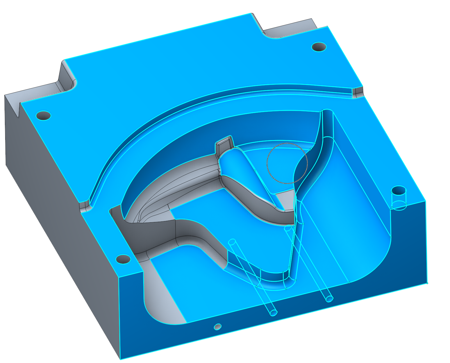
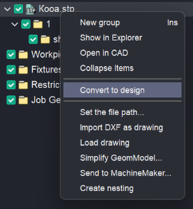
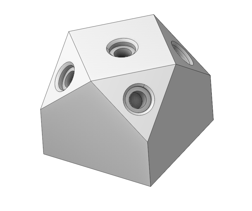
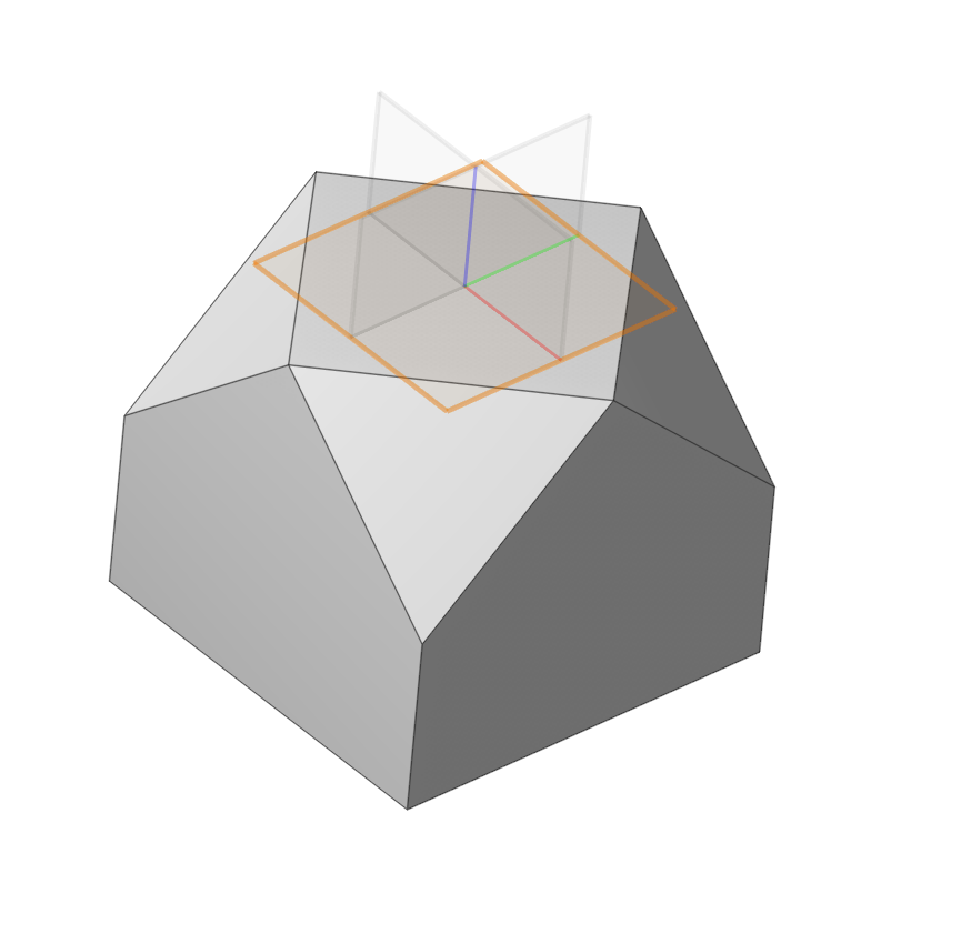
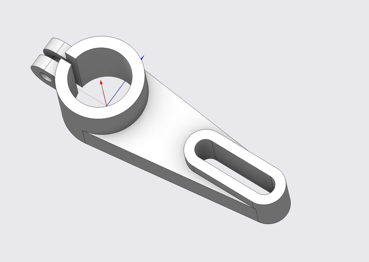
Improved option for Convert to design
The option allows you to transform the model and open it in Design mode. In it, you can simplify the model using the Design mode tools for removing surfaces (Delete face). See more
This will allow you to quickly create a blank or simplify the model (remove a hole, pocket, etc.) to simplify processing.
The process for creating stock from a 3D part model is detailed in the following section.
See more
Design module enhancements
Design in 2D mode.
Fields for entering point coordinates.
Added fields for entering point coordinates for the following elements:
Contour (Contour point)
Arc by two points (Start point)
Rectangle by 2 points (Start point)
Rectangle from center (Center point)
Circle (Center point)
When creating a contour, the ability to insert coordinates of a set of points from the clipboard is added. See more
Design in 3D mode.
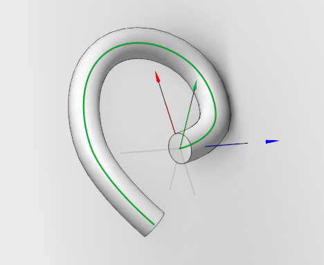
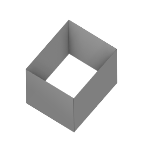
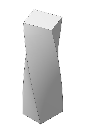
Added a sweep.
Stretching the profile along the trajectory. The profile can be a closed or open outline sketch (Profile). The contours of a sketch, spatial curves, and edges of bodies can act as a Path. See more
Implemented Delete Face functionality.
Allows you to remove elements of a part (holes, grooves, chamfers, etc.) See more
Other updates
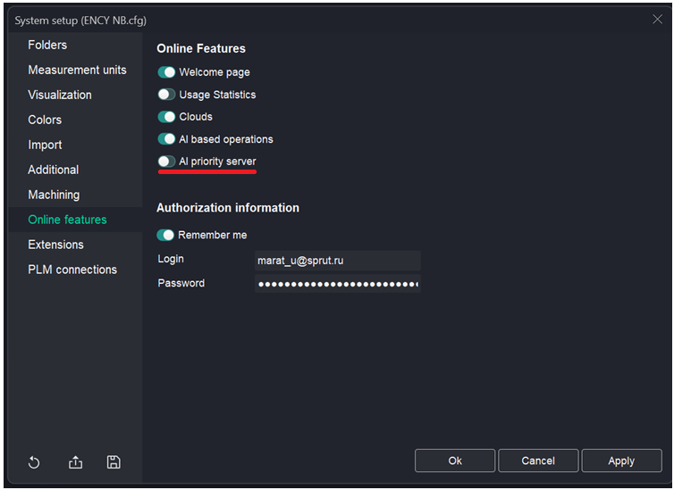
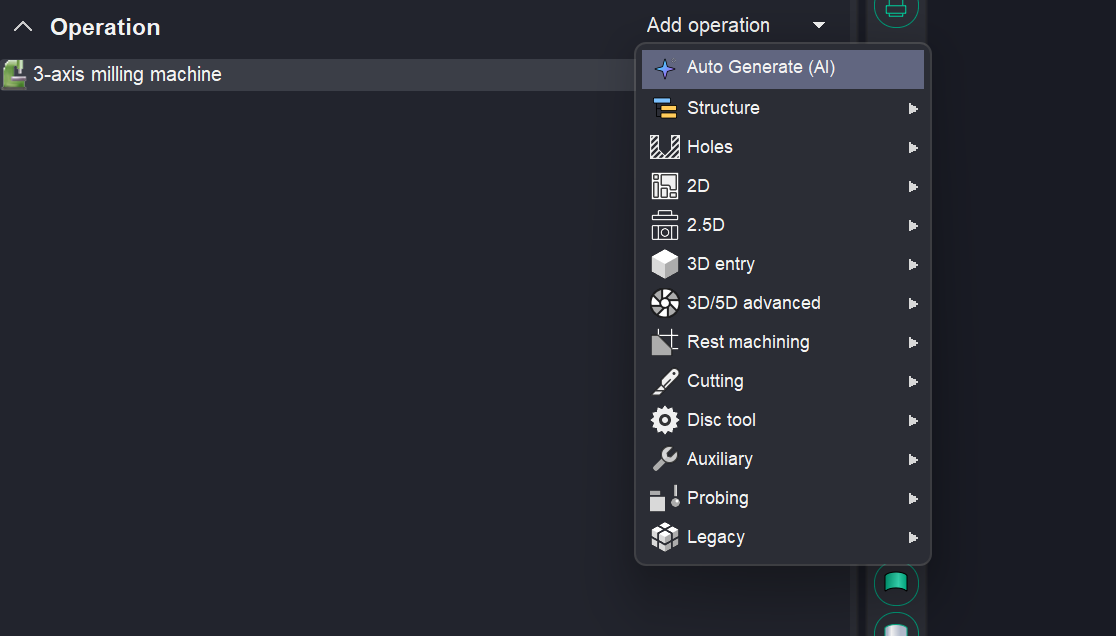
Added auto generation function (AI)
Part model analysis functionality has been integrated into the current project. This enhancement allows for the automatic incorporation of operations from our AI-powered knowledge base, streamlining the creation of standard manufacturing processes.
The option is enabled in the settings and is available when creating an operation.
Update to MachineMaker.
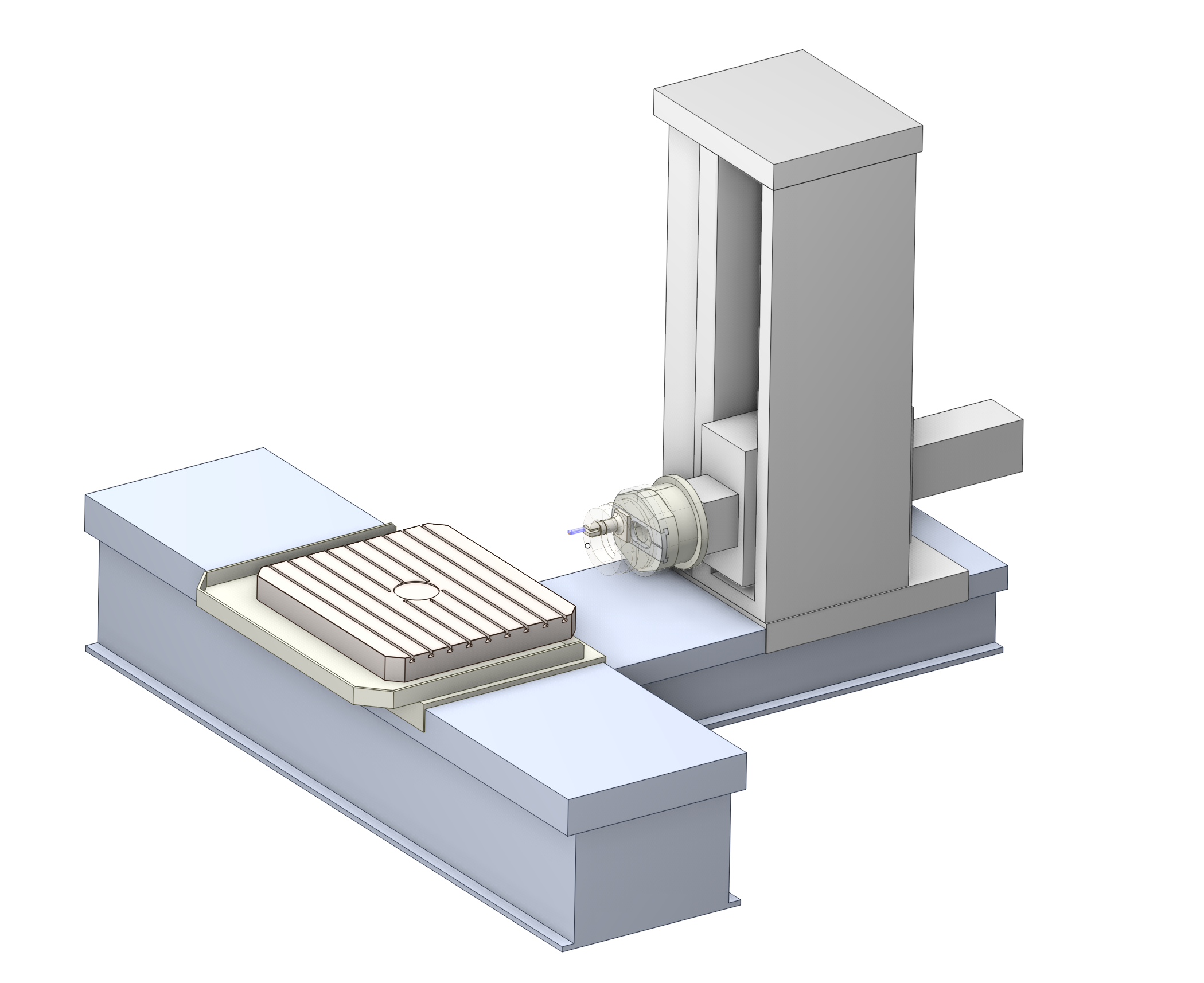
Trevisan machines are now supported in MachineMaker
T
he assembly process of such machines in MachineMaker involves adding the machine base and attaching the Multi Tool Head. Currently, this head is configured with basic kinematics similar to a D'Andrea head, but users can freely modify the kinematics, attach any number of tool blocks, and configure them as needed. The assembly is similar to lathe milling machines but simpler. At the moment, there are no templates or restrictions, allowing the creation of a fully customizable Multi Tool Head. See more.
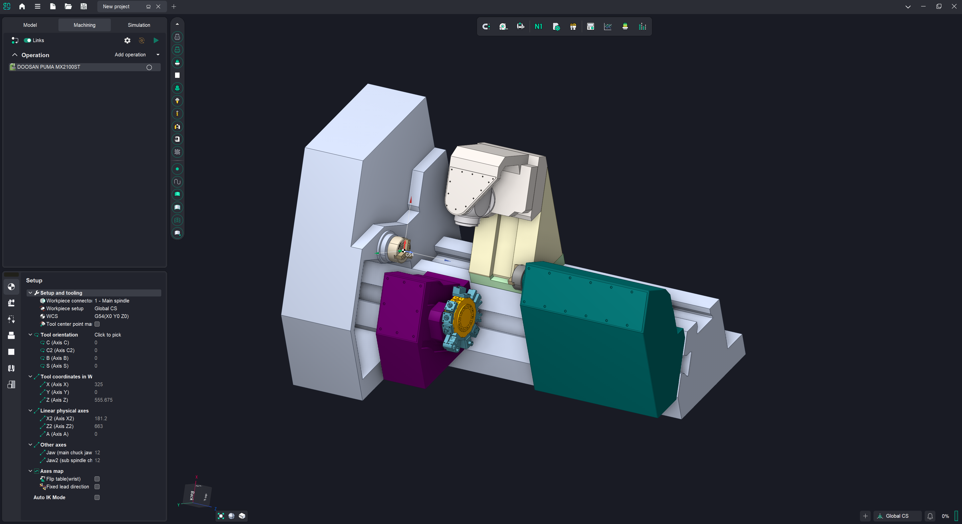
The functionality of working with lathe milling machines has been improved
Machines with a double revolver are available for creation in MachineMaker. See more.
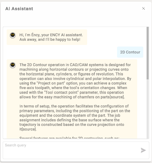
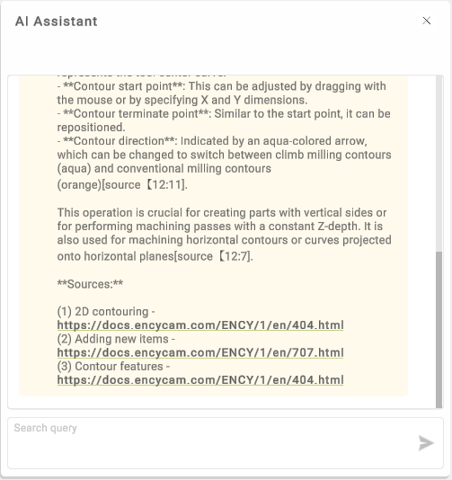
The AI assistant in MachineMaker has been updated.
The MachineMaker AI assistant has been significantly upgraded. It now has access to the complete CAM system and MachineMaker documentation. Ask any question, and the assistant will find the answer directly from our resources.
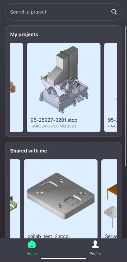
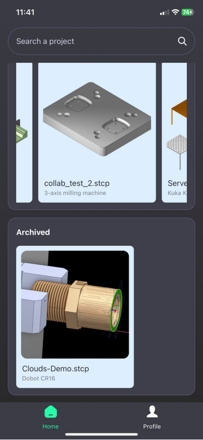
Clouds has been updated
Clouds has been updated with a fresh new design! We’ve also enhanced the chat experience by introducing video recording, and the ability to edit and delete your messages.
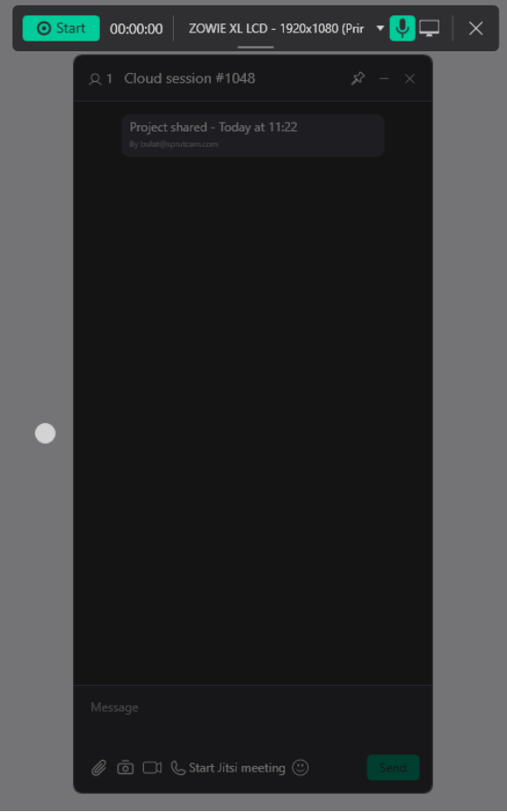
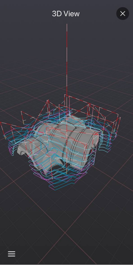
Working in Clouds is now even easier with the new ENCY Clouds mobile app! Available on Android and iOS, the app lets you do everything you can do on the desktop version.
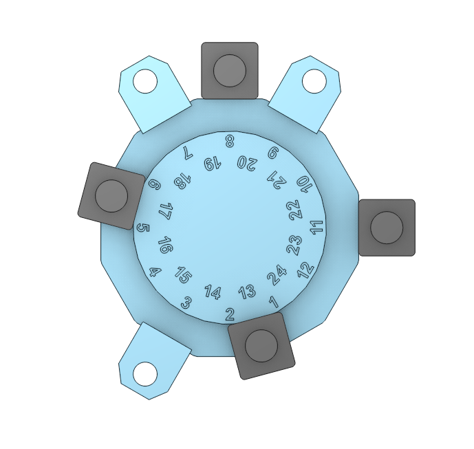
You can view the 3D model used in the project.
New version ENCY Tuner 2 available
New UI. With the new and improved, more intuitive navigation, users can now locate information significantly faster.
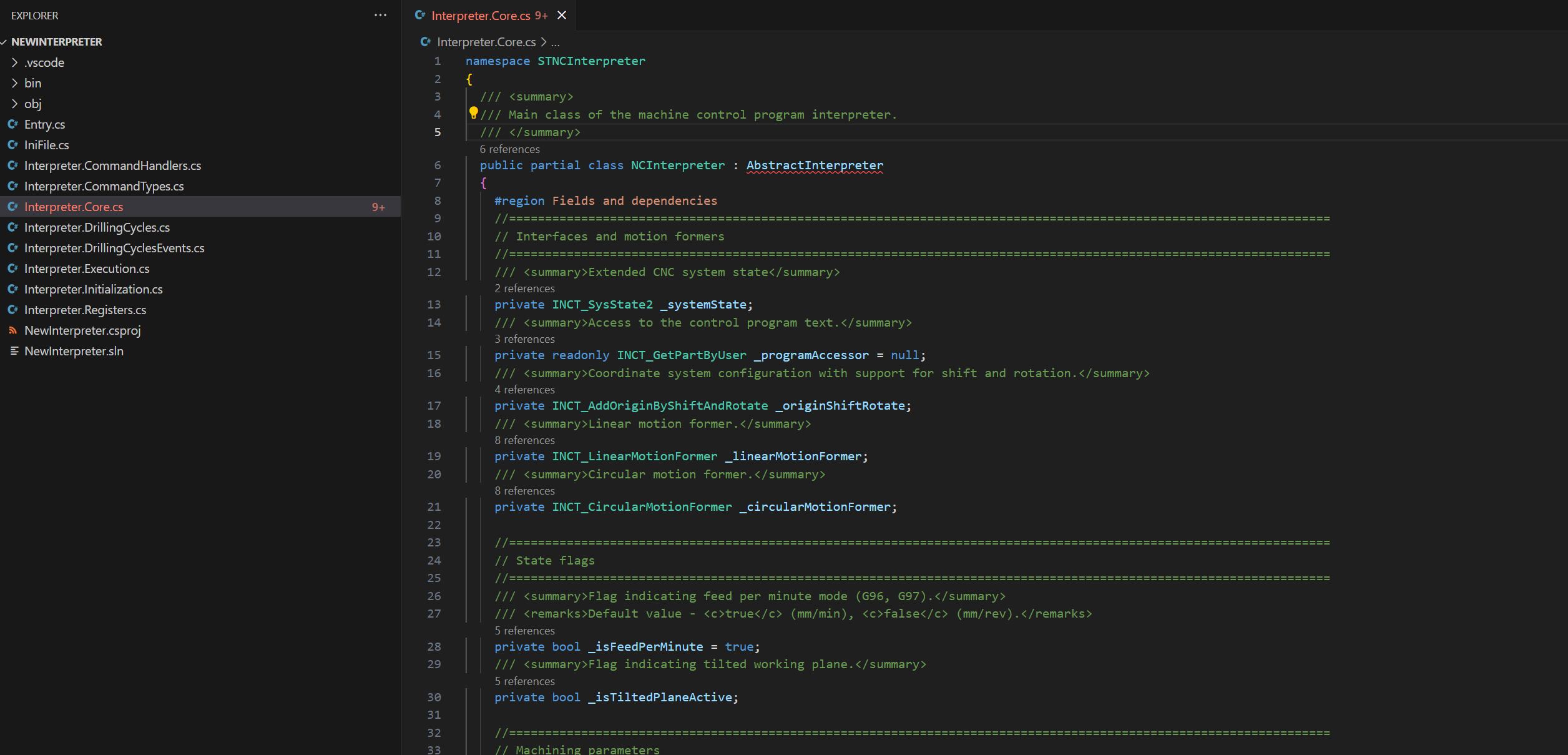
Typical interpreter templates in the C# (C Sharp) language have been added.
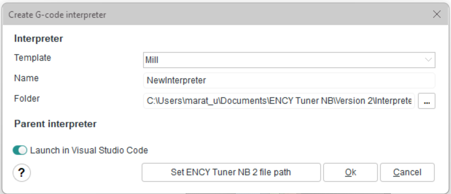
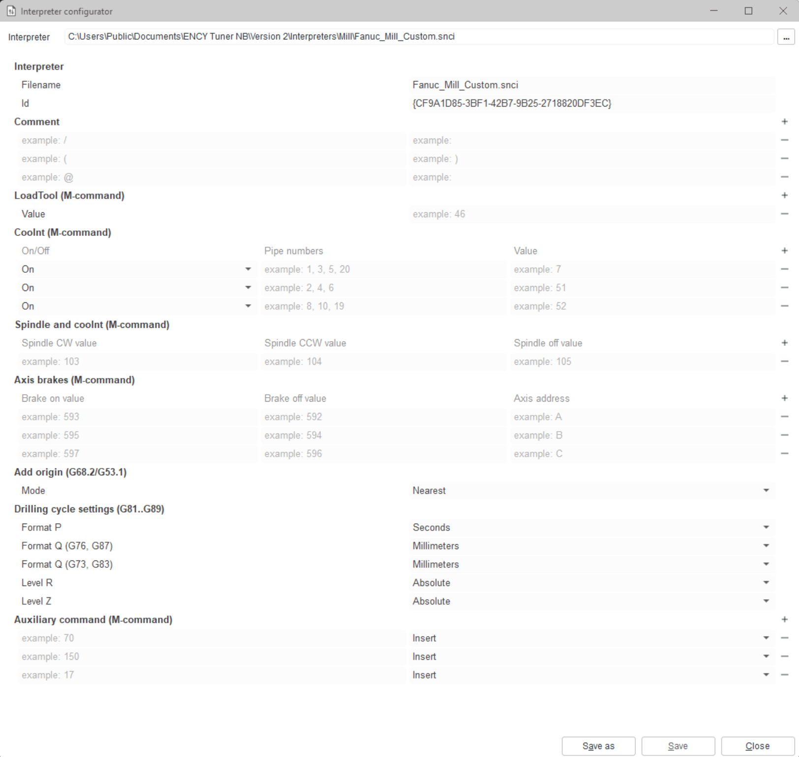
Interpreter Configurator. Provide ease of creating interpreters. Create an interpreter without programming. We create universal interpreters with the ability to manually configure via UI ("checkboxes").
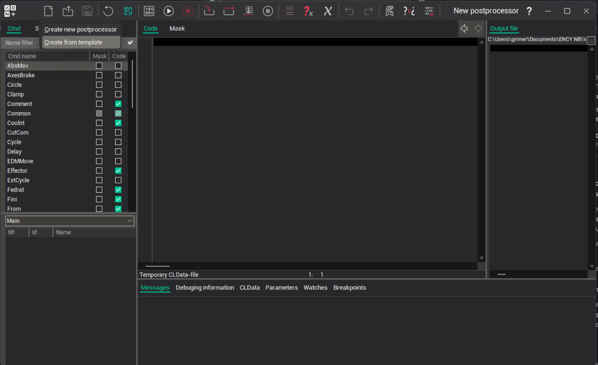
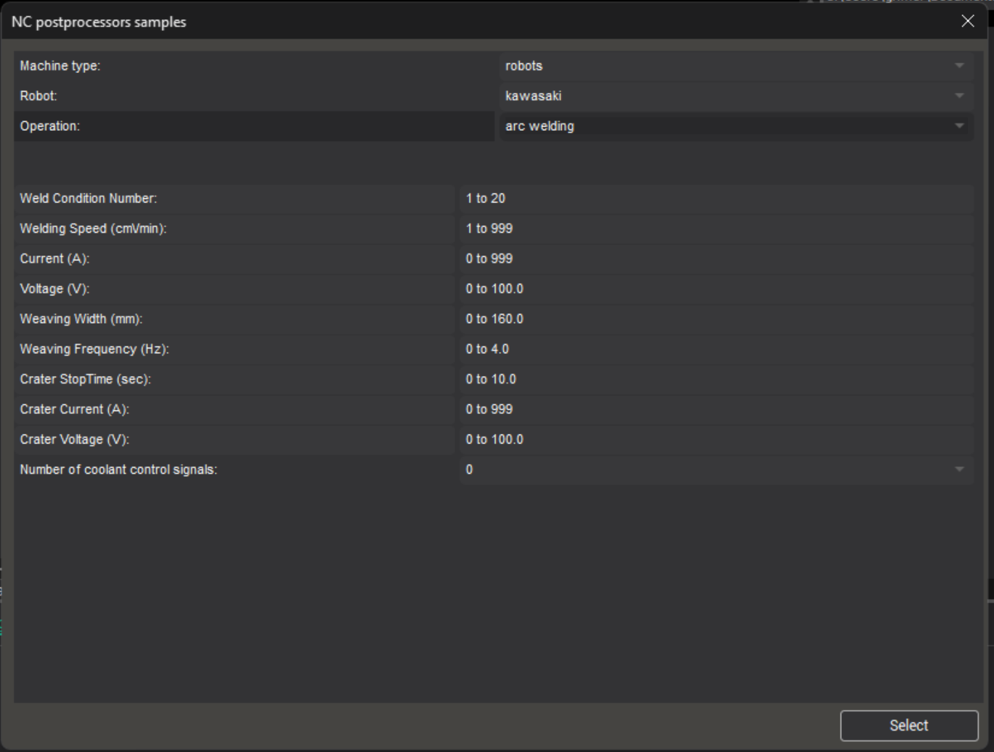
INP template postprocessor
A new feature has been introduced in ENCY 2 — the ability to create postprocessors based on a customizable template.
Users can now open a new window to select the type of postprocessor (e.g., robot or CNC machine) and define the main parameters through an intuitive interface.
Key benefits:
Fast and easy creation of a basic postprocessor without needing to dive into the details;
A standardized template simplifies developers’ work, speeding up both creation and maintenance of postprocessors.