Non-planar slicing
Application area:
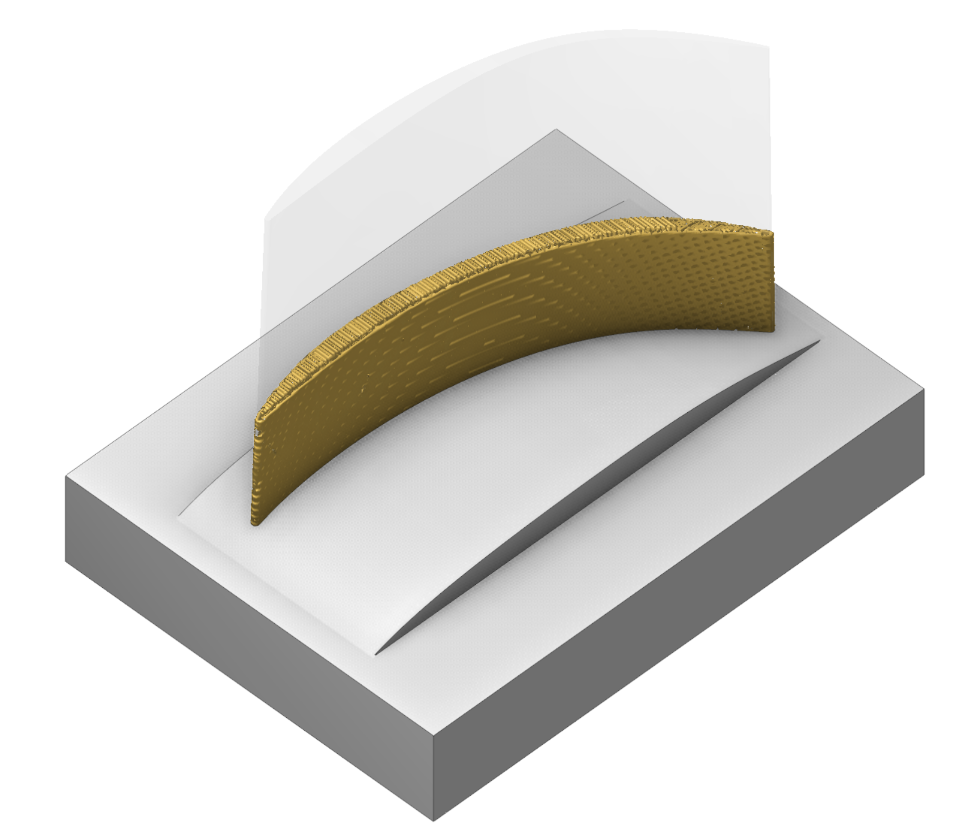
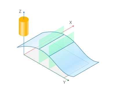
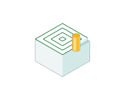
This operation allows you to print models on arbitrary substrates. It uses a non-planar slicer engine and generates a non-planar additive printing path. But also it's possible to generate a classic planar printing path with some extra parameters.
Setup:
The Setup tab is used to configure the primary parameters of the project. This can involve the positioning of the part on the equipment, the coordinate system of the part, and more. See more
Job assignment:
Non-planar substrate. Substrate for printing (for "Offset" strategy only)
Feature. Desired model, that should be printed
Properties. Disabled
Delete. Removes an item from the list
Strategy:
Slicing strategy.
Defines the slicing strategy.
Strategy types
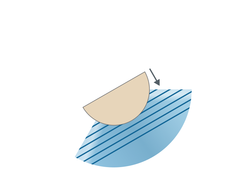
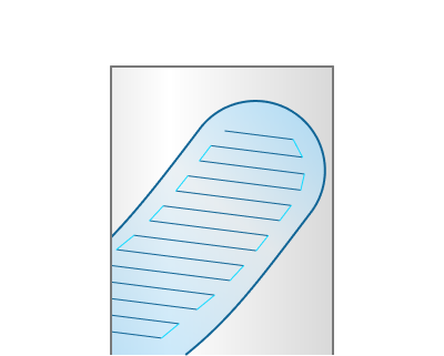
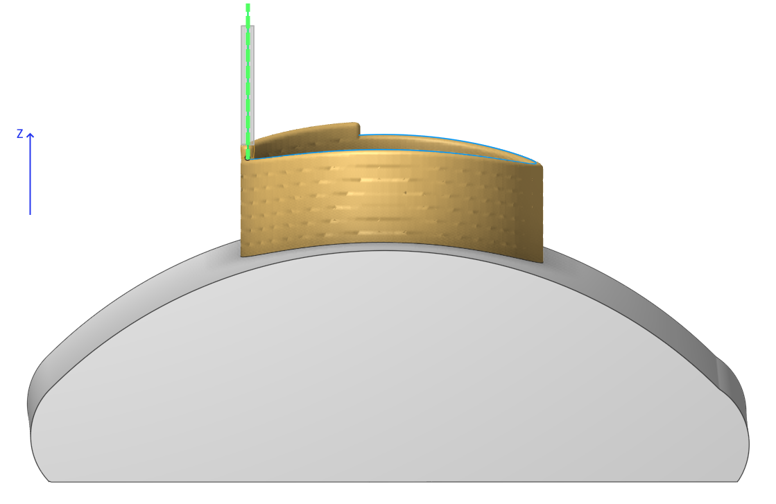
Planar. This strategy performs classic planar slicing, but supports different slicing directions and allows changing the toolpath normals.
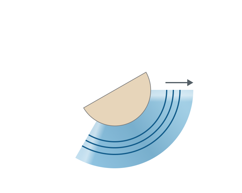
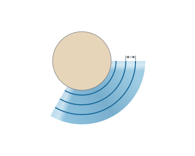
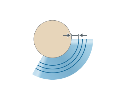
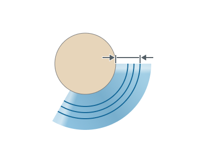
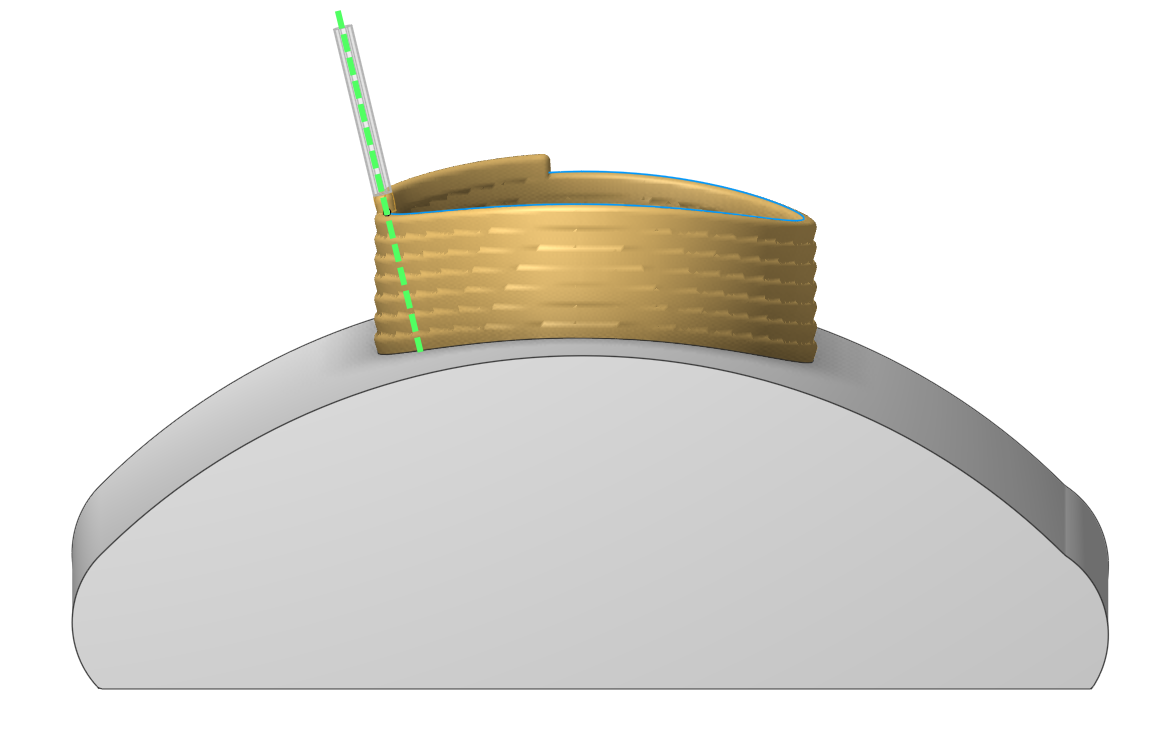
Offset. This strategy performs slicing by offset method from the substrate, which allows to maintain a constant layer height between each layer.
Common parameters
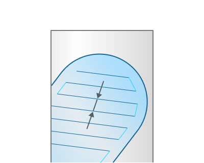
Layer height. Height of each layer in mm. By default corresponds to the working length (WL) of the tool.
Line width. Width of a single line. By default corresponds to the diameter of the tool
Planar slicer parameters
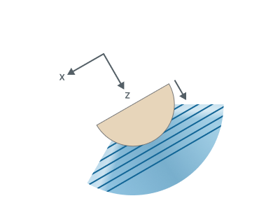
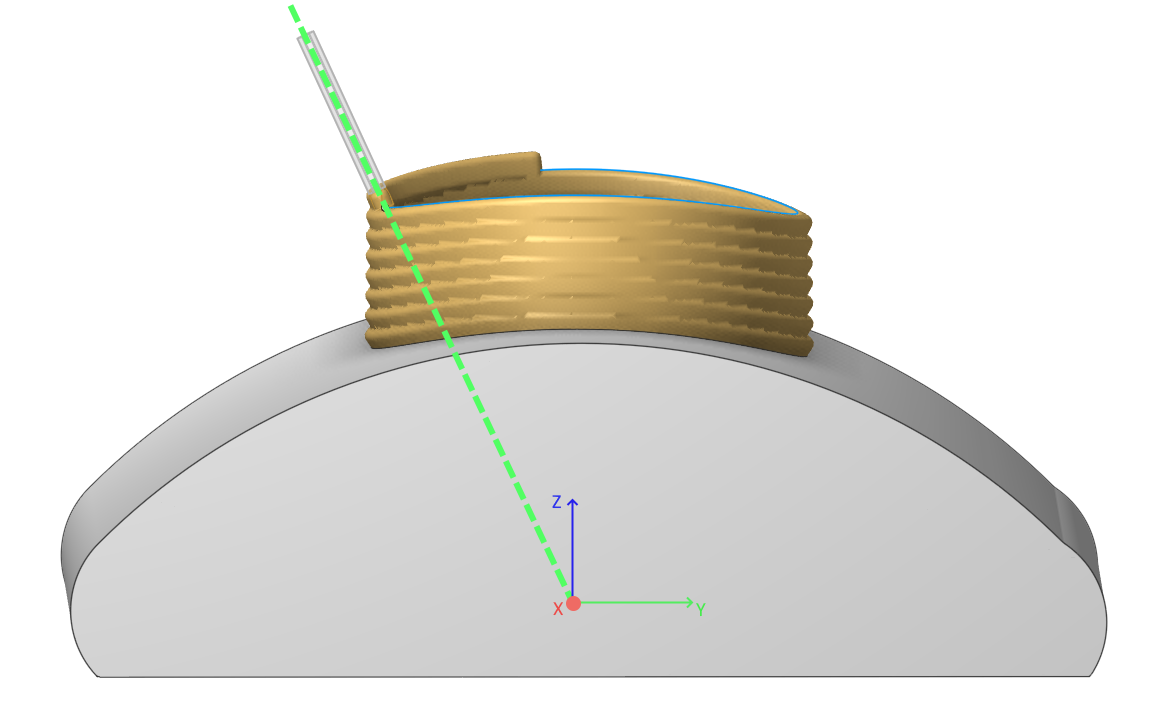
Slicing direction. Specifies the slicing direction for the "Planar" slicing strategy - along the X, Y, Z axis or a custom direction.
Offset slicer parameters
Surface resolution level. Represents the resolution level of the offset surfaces that will be constructed to split the model. Lower values produce faster result, but in lower resolution. Higher values produce slower result, but in higher resolution.
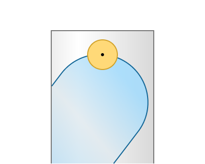
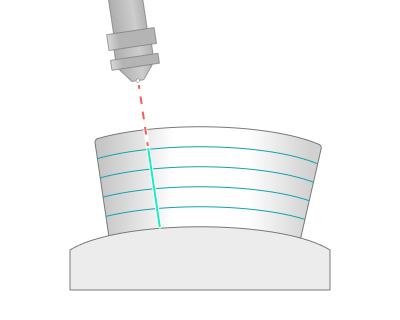
Start offset. The offset value from the substrate, where the printing process will start
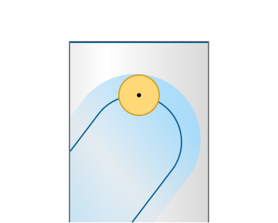
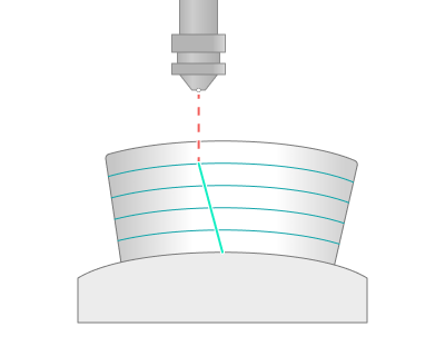
End offset. The offset value from the substrate, which represents the finishing boundary of the printing process. However, it may stop earlier depending on the layer height parameter.
Print inner volume.
Offsets the tool path into the model by half of the line width value
Infill.
A group of parameters to generate an infill for the model.
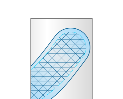
Infill pattern. Defines the infill pattern.
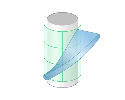
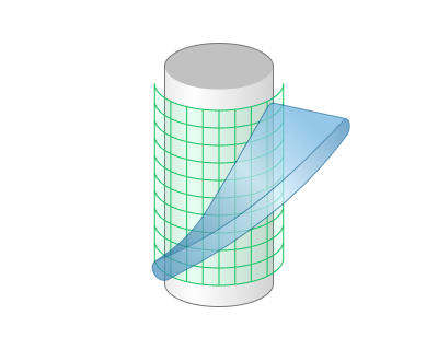
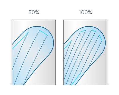
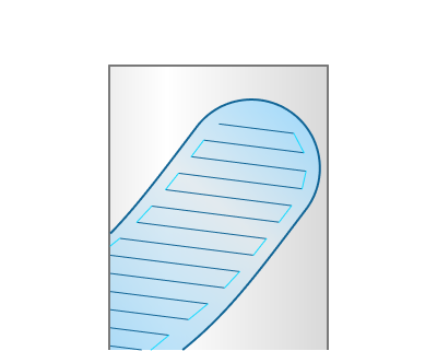
Lines. This infill pattern is created by intersecting non-planar layers with simple vertical planes

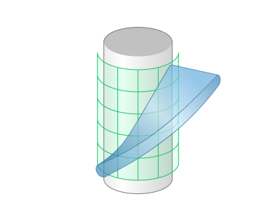
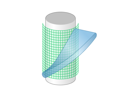
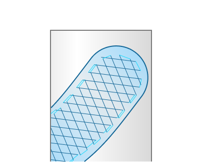
Grid. This infill pattern is created by intersecting non-planar layers with vertical planes in such a way that it forms a grid

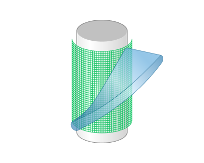
Triangles. This infill pattern is created by intersecting non-planar layers with vertical planes in such a way that it forms equilateral triangles
Infill orientation. Determines the orientation of the infill in 3D space.
Direction. The direction vector of the infill. By default corresponds to the tool orientation vector for the "Offset" strategy and to the slicing direction vector for the "Planar" strategy.
Tool orientation vector. Tool orientation can be set on a Setup page. See more
Slicing direction vector. Corresponds to the slicing direction vector, which you can set in the parameters of "Planar" strategy.
Custom. Allows you to manually set the normal vector and rotation angle for the infill.
Infill density. Adjusts the density of the infill as a percentage.
Alternate lines direction. Alternate lines direction on each layer by 45 degrees
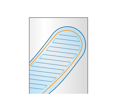
Double walls.
Adds an additional inner wall.
Sorting.
Toolpath sorting and linking parameters.
Sort by.
Allows to set printing order of layers and features.
Layers. Allows to print all features layer by layer.
Features. Allows to print all features one by one (Note: To use this option correctly, you must configure your features as separate elements on the Job Assignment page).
Split by layers.
This parameter allows you to split your features into a desired number of layers. It is available only when the "Sort by" parameter is set to "Features" option.
Note: This parameter is useful when printing feature by feature is not possible due to collisions with previously printed features. It also helps to achieve more even heat distribution across the printed elements and to reduce residual stress.
Start points.
Allows to set custom rules for deciding starting point on print layers.
Auto. The start point is chosen automatically
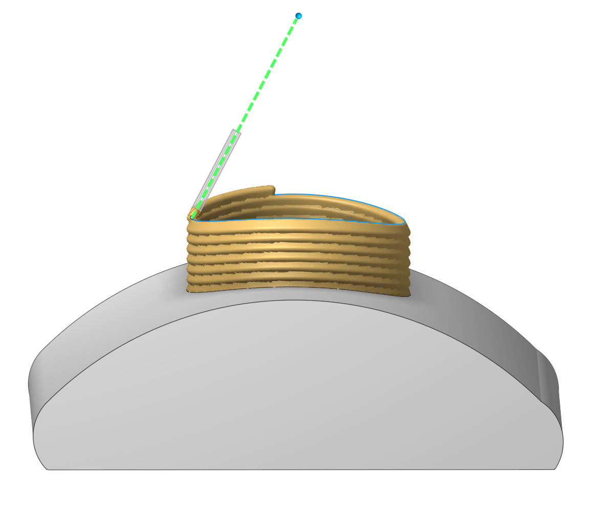
Custom for first layers. Allows to manually choose the start point for the first layer of features. Start points for subsequent layers are determined by the closest distance to the start point of the previous layer. You can set them on the Job assignment page.
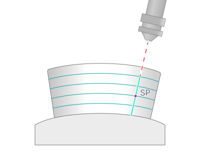
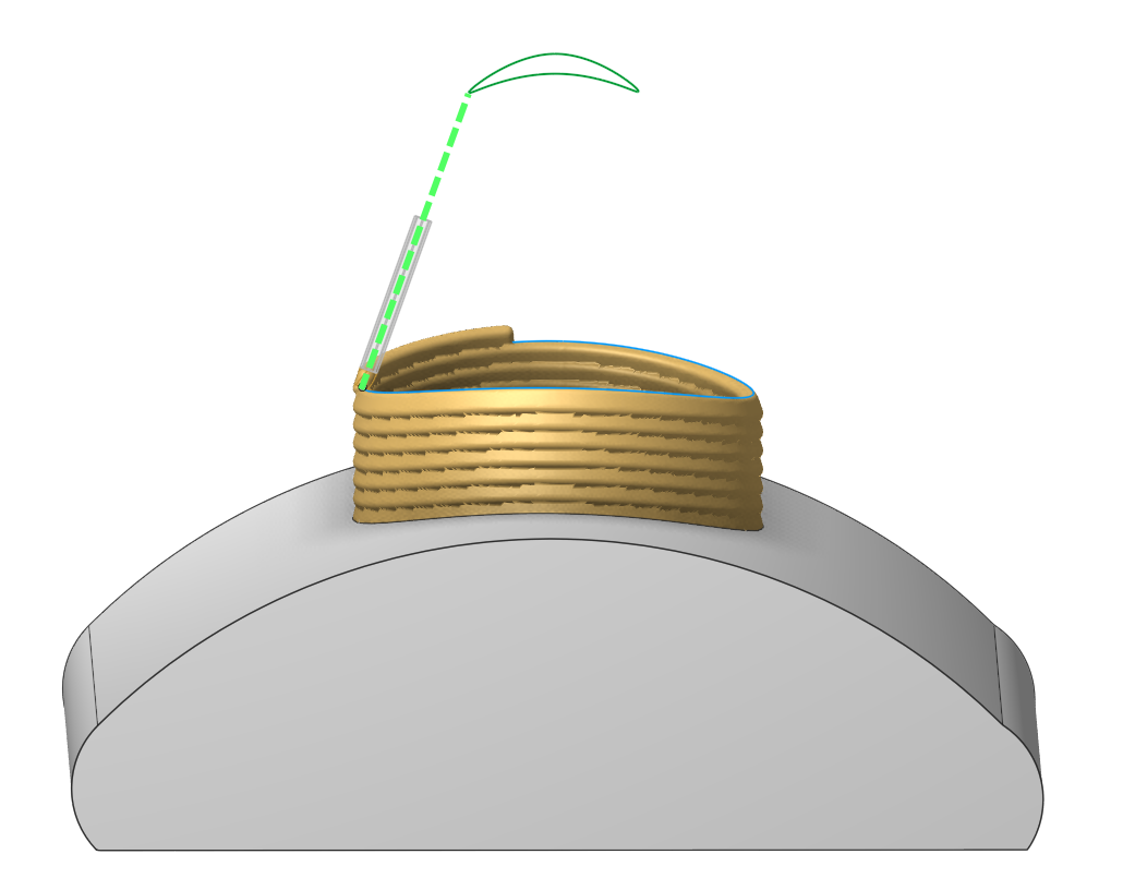
Custom for all layers. Allows to set start points for all layers by setting a curve. In this case, the start points are calculated based on the nearest distance to a specified curve. You can set them on the Job assignment page.
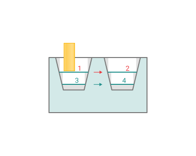
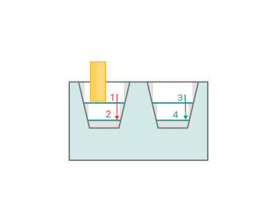
Printing order.
Determines the order of walls and infill when printing.
Inside to outside. Infill will be printed first, after that inner walls and outer wall.
Outside to inside. Outer wall will be printed first, after that inner walls and infill.
Alternate directions. The printing order will alternate layer by layer, starting from "Inside to outside" order.
Tool orientation.
This parameter allows you to set different tool orientation (normal) without changing the original toolpath. There are five options avalaible for users: "Normal to surface", "Fixed", "To rotary axis", "Through point" and "Through curve".
Normal to surface.
Fixed.
To rotary axis.
Through point.
Through curve.
More information about the "Tool orientation" parameter can be found in the description of the "5D Surfacing" operation. See more.
Limit rotation angles.
When the flag is set, it specifies the limit values of the tool's angular position relative to the specified axis. This parameter group works similarly to the " 5D Surfacing" operation . See more.
Parameters:
Output Interpolation.
Using interpolation is one of the main ways to modify the path, allowing you to adjust smoothness and the concentration of points on trajectory. See more.
Minimum Layer Time.
This parameter allows you to set the minimum allowed time in seconds for printing a single layer. See more.
Simulation.
Determine the parameters for the simulation output settings. See more.
Links/Leads:
In the Links/Leads tab, you define the parameters for rapid movements. These movements include tool approach from the tool change position, engage to the start of the working stroke, retraction after the final cutting motion, transitions between working passes, and return to the tool change point. You can configure the sequence of movements along the coordinates, the trajectory of these motions, and the magnitude of displacements.
Feeds/Speeds:
Using this dialogue the user can define the rapid feed value and the feed values for different areas of the toolpath. Also it's possible to apply "Corner control" parameters on this page. See more
Transformations:
Parameter's kit of operation, which allow to execute converting of coordinates for calculated within operation the trajectory of the tool. See more
Important note
The "Multiply scheme" parameter in this operation behaves differently compared to other operations.
Normally, this parameter duplicates the entire toolpath of the operation - including the slicing results and the links/leads between layers.
However, in this operation, it only duplicates the slicing result before the linking stage.
This allows to multiply features and apply settings like "Links/Leads" or "Split by Layers", which would not be possible using the standard multiplying method.
Part:
A Part in additive manufacturing is a desired geometry to be manufactured by the printing process . See more
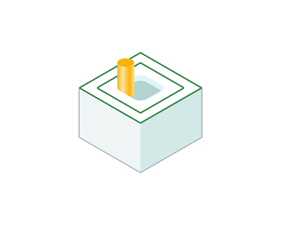
Workpiece:
A Workpiece in additive manufacturing is t he pre-existing material or substrate that serves as the foundation for printing (can be empty) . See more
Fixtures:
As the Fixtures the fixing aids such as chucks, grips, clamps, etc., and the restriction areas of any other nature are usually specified. See more