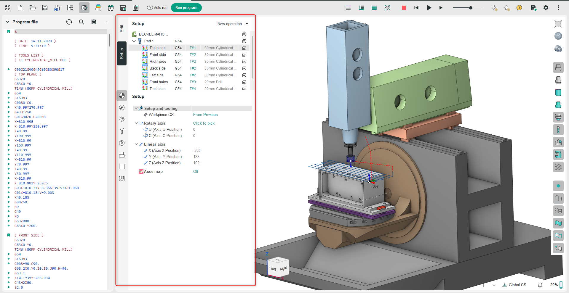
Working mode Setup

Application Area:
In setup mode, users can access a wide range of tools for configuring and modifying the process parameters shown in the Main Panel. The functions and commands available are identical to those in the CAM system and depend on the currently selected level in the operations tree. The operation tree includes the following levels:
Machine. This level provides access to tools for viewing and adjusting the parameters of equipment and fixtures.
Setup Stage / Part (Group). A Setup Stage defines a stage of the technological process executed while the workpiece remains in a constant position. The Part (group) is used in multi-component projects. These can be several different (design) parts or standard parts divided in the technology by operation, similar to a conveyor. See more.
Operation, This level provides tools for configuring the parameters of a specific technological operation.
Configuration tools for operation parameters are arranged in the following tabs:
Setup.
The Setup tab is used to configure the primary parameters of the project. This can involve the positioning of the part on the equipment, the coordinate system of the part, and more. This tab is available at all levels of the operations tree.The parameters on the tab are the same as in the CAM system. See more.
Machine Setup.
This tab is necessary for configuring the fundamental project parameters, primarily related to the kinematic scheme of the equipment. This tab is available at the Machine level of the operations tree. The parameters on the tab are the same as in the CAM system. See more
Strategy.
This tab provides the ability to customize certain aspects of the tool path calculation. This tab is available at the Operation level of the operations tree. The parameters on the tab are the same as in the CAM system.
Parameters.
This tab allows the configuration of parameters for toolpath output. This tab is available at the Operation level of the operations tree. The parameters on the tab are the same as in the CAM system. See more
Tool.
This tab allows the configuration of tool parameters. This tab is available at the Operation level of the operations tree. The parameters on the tab are the same as in the CAM system. See more.
Feeds/Speeds.
This tab is designed for configuring cutting speed and feed rates. This tab is available at the Operation level of the operations tree. The parameters on the tab are the same as in the CAM system. See more.
Part.
This tab provides the functionality for creating and loading the technological object — Part. A Part is a group of geometrical elements that defines the space to check for gouges. This tab is available at all levels of the operations tree. The parameters on the tab are the same as in the CAM system. See more. Unlike a similar tab in the CAM system, this option allows directly importing a 3D model of the part. In the Add Surfaces dialog box, you can open Windows Explorer to select the model file. This dialog also allows you to remove the model from the project list.
Workpiece.
This tab provides the functionality for creating and loading the technological object — Workpiece. A workpiece model of an operation defines the material to be machined. This means that it defines the initial shape of the workpiece from which the required finished component will be produced. This tab is available at all levels of the operations tree. The parameters on the tab are the same as in the CAM system. See more. Unlike a similar tab in the CAM system, this option allows directly importing a 3D model of the workpiece. In the Add Surfaces dialog box, you can open Windows Explorer to select the model file. This dialog also allows you to remove the model from the project list.
Fixtures.
Use this tab to include and set up kinematic schemes for fixtures in the project. This tab is available at all levels of the operations tree. The parameters on the tab are the same as in the CAM system. See more