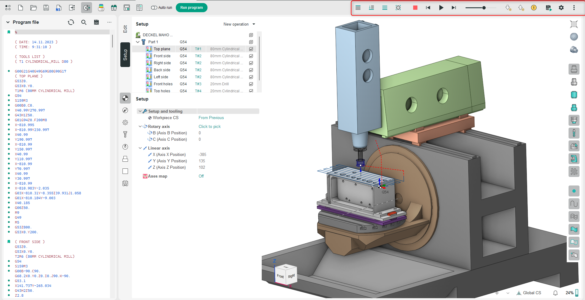
Simulation Panel

Application Area:
Contains tools for modifying simulation parameters and presenting the results. Machining simulation mode allows the user to obtain an image of the model being machined during the machining process. This allows the user to visually check the machining quality, analyze the presence of any rest material and over-cuts. The main tools and functions on this panel are the same as those in the CAM system. See more.
Tool motion controlling:
The operation of these commands follows the same principle as in the CAM system. See more.
Simulate Current Operation.
The function runs the fast simulation of the selected operation. All NC commands inside the selected operation are run. The simulation stops when the next operation attained. Screen performs once upon completion of the simulation.
Simulate up to Current Operation.
The function runs the fast simulation till the current operation. Work off all commands from the beginning of technological process and up to the selected node path or operation. Screen performs once upon completion of the simulation.
Simulate All Operations.
The function runs the fast simulation all operations at once. Screen performs once upon completion of the simulation.
Delete Chips.
The function deletes chunks of the workpiece (or simply, chips) that do not contain the part geometry. See more.
Reset.
The function resets the workpiece to its initial state. To drop the simulation results, one should press this button. When pressed, the workpiece will be reinitialized according to the parameters defined in the root node of the machining tree.
Step Backward.
The command simulates the instruction of the NC program before current one. The screen updating depends on the tool movement method.
Run.
The command runs the step-by-step simulation from the current NC program instruction to the end of the technological process. The screen updating depends on the tool movement method.
Stop.
The command stops the simulation process.
Step Forward.
The command runs the simulation from the current NC program instruction. The process stops after the next motion instruction arrival.
Speed adjustment.
User can control the visual speed of the tool by altering the tool speed slide. The far left position is the slowest movement speed, the far right – the fastest.
Toolpath Errors Detecting:
The operation of these commands follows the same principle as in the CAM system. See more.
Go to Next Error.
Jump to the NC program block with the next error.
Go to Previous Error.
Jump to the NC program block with the previous error.
Checks and Stops.
Allows you to set which types of errors will be verified and define the simulation's response when errors are found.
Control of the Simulation View and Results:
Save.
The function saves the simulation result to an STL file. Save the simulation result that is on the screen to the file. Input the exported file name in the STL format. The file you will get can be used as a workpiece in the another project or in the any software that can import STL file format.
Simulation Parameters.
Enables adjustment of the accuracy for displaying trajectories and models during simulation. Set the parameters similarly to those in the CAM system. See more.
Smooth Simulation.
Controls the movement continuity mode along the trajectory during simulation. When the <Smooth> method is selected (checked this option), the tool will move smoothly with constant speed. In this mode, user can control the visual speed of the tool by altering the tool speed slide. The far left position is the slowest movement speed, the far right – the fastest. If <By block> is selected (unchecked this option), then the tool will move block-by-block, with drawing at intermediate points only.
Rapid Motion.
Allows setting the relative simulation speed for toolpath segments with idle movements.
Compensation Curve.
For operations that use tool radius correction in Control mode, activating this option shows the trajectory of the tool's center.
Type.
Adjusts the rendering of the 3D model of the workpiece during simulation.