Optimized plane operation (plane-plane)
Application area:
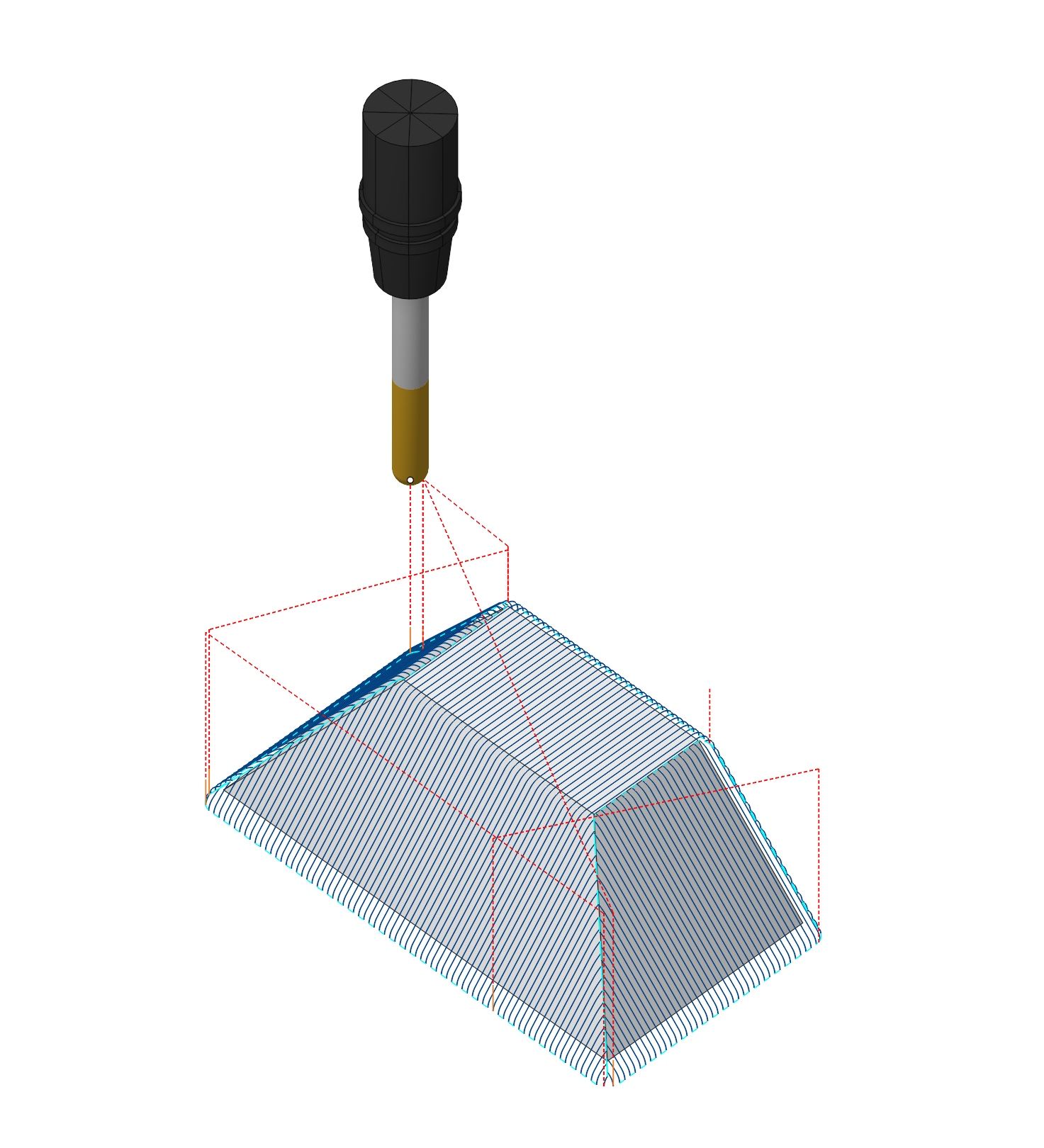
The optimized plane toolpath consists of two finishing plane passes lying in mutually perpendicular planes. Each pass machines only those areas where the frontal angle of the surface slope measured relative to the cutting direction is 45 degrees or less. This ensures that no surface is machined twice. And thanks to that a consistent scallop height across entire part is achieved. This makes optimized plane a good choice for high quality finishing machining of complex parts.
Setup:
The Setup tab is used to configure the primary parameters of the project. This can involve the positioning of the part on the equipment, the coordinate system of the part, and more. See more
Job assignment:
Faces. Select various surfaces of the part as the working task. The system will calculate the trajectory based on the chosen surfaces. See more
Pocket. A typical prismatic or turn-milling part consists of many simple shapes.To simplify this task, we can recognize the parts elements in a 3d model and automatically convert them to basic job assignment items, such as job zones and machining levels. See more
Job Zone. Job zones are used to define the part areas that have to be machined by roughing and finishing milling operations. See more
Restrict Zone. In addition to Job Zones in system you can use Restrict Zones to specify the workpiece areas that have not to be machined in the current operation. See more
Top Level. Specifying the top level by model elements. See more
Bottom Level. Specifying the bottom level by model elements. See more
Properties. Displays the properties of an element. It is possible to add the stock. You can also call this menu by double clicking on an item in the list.
Delete. Removes an item from the list.
Restrictions. It allows you to restrict areas that should not be machined. See more
Links/Leads:
In the Links/Leads tab, you define the parameters for rapid movements. These movements include tool approach from the tool change position, engage to the start of the working stroke, retraction after the final cutting motion, transitions between working passes, and return to the tool change point. You can configure the sequence of movements along the coordinates, the trajectory of these motions, and the magnitude of displacements.
Feeds/Speeds:
Using this dialogue the user can define the spindle rotation speed; the rapid feed value and the feed values for different areas of the toolpath. Spindle rotation speed can be defined as either the rotations per minute or the cutting speed. The defining value will be underlined. The second value will be recalculated relative to the defining value, with regard to the tool diameter. See more
Transformations:
Parameter's kit of operation, which allow to execute converting of coordinates for calculated within operation the trajectory of the tool. See more
Part:
A Part is a group of geometrical elements that defines the space to check for gouges. See more
Workpiece:
A workpiece model of an operation defines the material to be machined. See more
Fixtures:
As the Fixtures the fixing aids such as chucks, grips, clamps, etc., and the restriction areas of any other nature are usually specified. See more
See also:
Operations for the 3-axes milling