Panel for working Project Setup
Application Area:
This panel allows for managing the process’s technology tree: creating operations, defining the part model, and more.
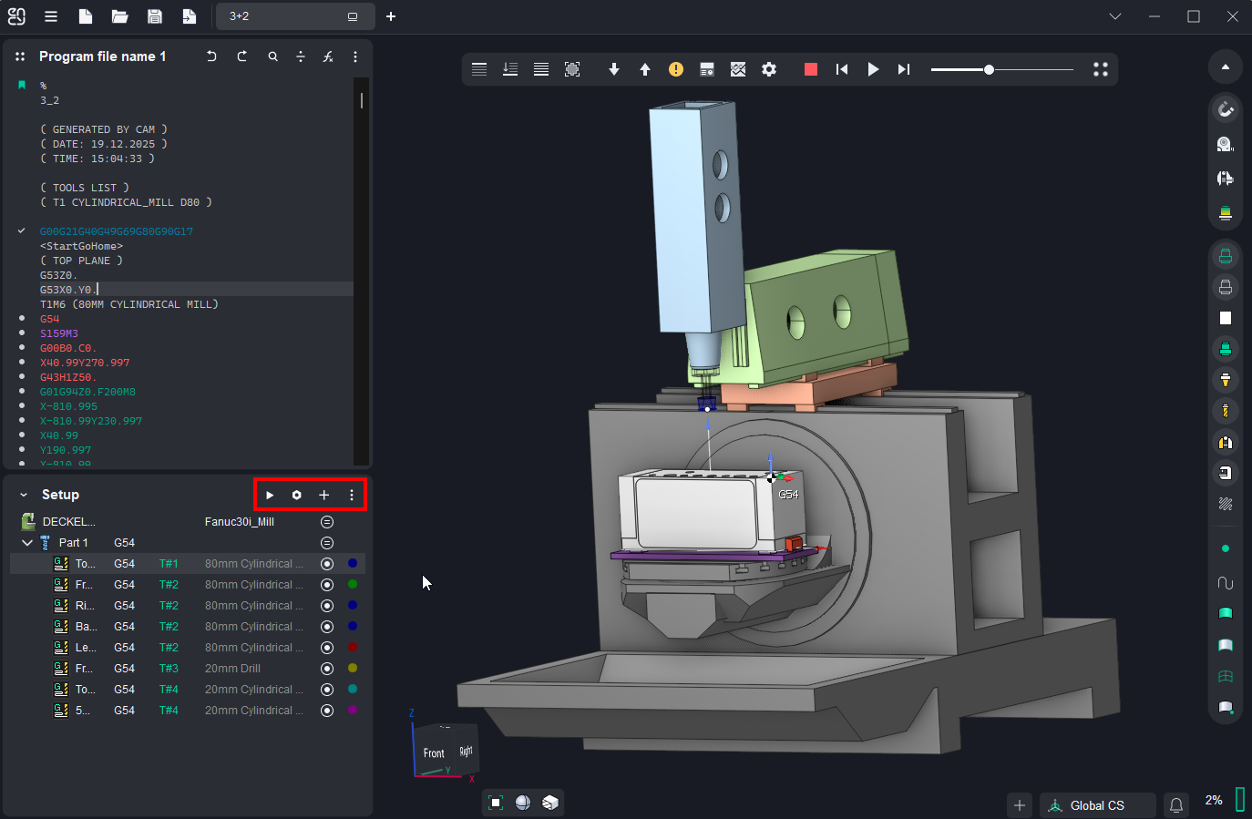
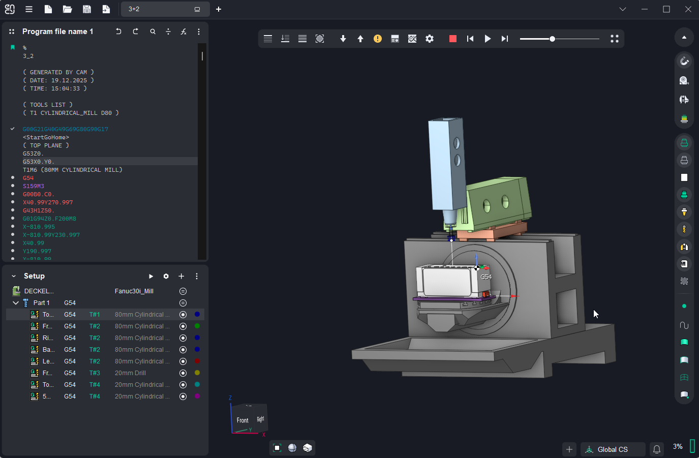
Run program.
Pressing the button calculates the operations in the Main Panel window, displaying their trajectories. As a result, the operation status changes, and labels appear in each block of the NC program:
<
 > – NC block is not simulated;
<
 > – NC block is simulated without errors;
<
 > – NC block is simulated with error;
<
 > – NC block is idle. The stock is not removed by this tool motion command.
During the simulation process, the influence of the NC command on the workpiece is analyzed, and corresponding status is assigned to the command.
The following types of errors are checked:
 — Stock removal by rapid feed is forbidden. If the stock is removed and the feed rate is rapid, then the command is marked as an error;
 — Toolholder collision. If the toolholder touches the workpiece when the NC command is marked as an error;
 — Impossible to calculate the compensation. Tool radius compensation is performed while doing the simulation. The compensation value is defined in the operation parameter window on the tool bookmark. If compensation cannot be made for the NC command, then the motion is marked as an error;
 — Tool plunge cuttings with an angle exceeding the maximum value specified in the tool parameters are marked as errors.
 — Collision of machine nodes.
 — Gouging the part is detected (appears if
option in Operation Parameters inspector is enabled).
 — Axis travel over the limits.
 — Inappropriate tool and spindle rotation direction error.
The type of error is described in the hint that appears after a delay under the NC command with error.
Parameters.
Operation parametrs.
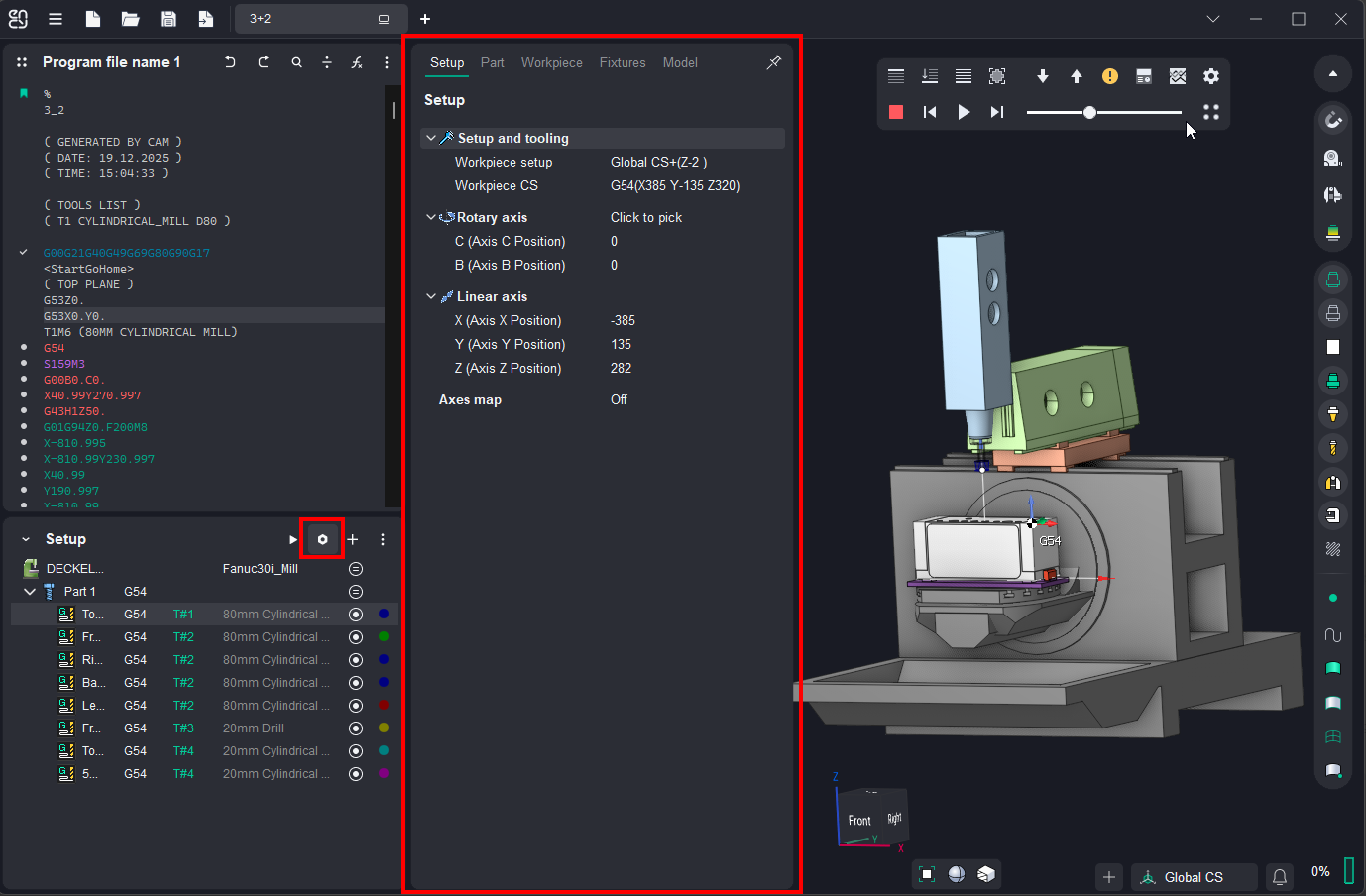
Setup.
The Setup tab is used to configure the primary parameters of the project. This can involve the positioning of the part on the equipment, the coordinate system of the part, and more. This tab is available at all levels of the operations tree.The parameters on the tab are the same as in the CAM system. See more.
Machine Setup.
This tab is necessary for configuring the fundamental project parameters, primarily related to the kinematic scheme of the equipment. This tab is available at the Machine level of the operations tree. The parameters on the tab are the same as in the CAM system. See more
Strategy.
This tab provides the ability to customize certain aspects of the tool path calculation. This tab is available at the Operation level of the operations tree. The parameters on the tab are the same as in the CAM system.
Use Advanced Toolpath Transformation. T his parameter converts the NC toolpath from machine to geometric. Which, in turn, makes it possible to correct the toolpath using the Step of Physic Movement Dividing. If the setting is disabled, then the final toolpath (in CLDATA format) is formed (as closely as possible repeating the one specified in the NC program), without the possibility of changing it.
Step of Physic Movement Dividing. Available only when using Use Advanced Toolpath Transformation (see above). In this mode, at the first stage, the tool path is converted into a geometric curve. At the next stage, machine movements are rasterized with the step specified in the current parameter to ensure maximum similarity with the original toolpath. The smaller the value of the rasterization step, the higher the accuracy of construction and, accordingly, the similarity with the original toolpath.
Radius Compensation Mode. A bility to disable or set an arbitrary compensation value on the tool radius.
Off. Radius compensation is disabled. Commands G40, G41, G42 in source NC code are ignored
Tool Radius. Radius compensation is equal to the tool radius. In the turning operations cutter radius compensation is equal to the tool nose radius.
Tool Radius Delta. Input the additional tool offset. The total offset is calculated as the sum of the tool radius and the value of this additional offset.
Custom Value. Radius compensation is determined by the specified arbitrary value.
Compensation Value. Input the arbitrary value for radius compensation. By default, the value is equal to the tool radius — 50% of the tool's diameter.
Parameters.
This tab allows the configuration of parameters for toolpath output. This tab is available at the Operation level of the operations tree. The parameters on the tab are the same as in the CAM system. See more
Tool.
This tab allows the configuration of tool parameters. This tab is available at the Operation level of the operations tree. The parameters on the tab are the same as in the CAM system. See more.
Feeds/Speeds.
This tab is designed for configuring cutting speed and feed rates. This tab is available at the Operation level of the operations tree. The parameters on the tab are the same as in the CAM system. See more.
Part.
This tab provides the functionality for creating and loading the technological object — Part. A Part is a group of geometrical elements that defines the space to check for gouges. This tab is available at all levels of the operations tree. The parameters on the tab are the same as in the CAM system. See more. Unlike a similar tab in the CAM system, this option allows directly importing a 3D model of the part. In the Add Surfaces dialog box, you can open Windows Explorer to select the model file. This dialog also allows you to remove the model from the project list.
Workpiece.
This tab provides the functionality for creating and loading the technological object — Workpiece. A workpiece model of an operation defines the material to be machined. This means that it defines the initial shape of the workpiece from which the required finished component will be produced. This tab is available at all levels of the operations tree. The parameters on the tab are the same as in the CAM system. See more. Unlike a similar tab in the CAM system, this option allows directly importing a 3D model of the workpiece. In the Add Surfaces dialog box, you can open Windows Explorer to select the model file. This dialog also allows you to remove the model from the project list.
Model.
This tab provides the functionality for importing 3D models into the project. A geometrical model in CAM system is represented as a tree of folders. Different geometrical objects are grouped in the folders. A working with the geometrical model structure is similar to the working with the files structure which is used in the Windows operating system. See more
Fixtures.
Use this tab to include and set up kinematic schemes for fixtures in the project. This tab is available at all levels of the operations tree. The parameters on the tab are the same as in the CAM system. See more
Add.
Allows for the creation of one of the main structural elements (setup, part, operation). See more
Postprocessor.
Generates a new NC program based on the technological operations displayed in the Main Panel window. See more.
Autorun.
When the feature is active, changing the NC program text will trigger an automatic recalculation of the operations displayed in the Main Panel window