Disc roughing
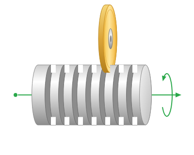
Application area:
The operation prepares stone for finishing by making cuts with a saw blade. The thin webs of material between the cuts are then removed manually by spalling, followed by finishing with an appropriate tool.
The primary tool is a saw blade. The operation also supports end mills and undercut tools. The descriptions and illustrations below refer to a saw blade.
Setup:
The Setup tab defines the part position on the machine, the coordinate system, and the main project parameters. Details
Job assignment:
The model to be machined is defined in the operation’s Part. The job assignment defines machining levels and restrictions.
Top level. Sets the upper machining limit using a selected geometric element. Details
Bottom level. Sets the lower machining limit using a selected geometric element. Details
Restrictions. Exclude specified areas from machining. Details
Strategy:
Toolpath:
Defines the arrangement of the cuts.
Click here to expand..
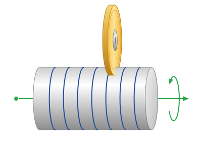
Rotary. Cuts are generated around the rotary axis and distributed along it.
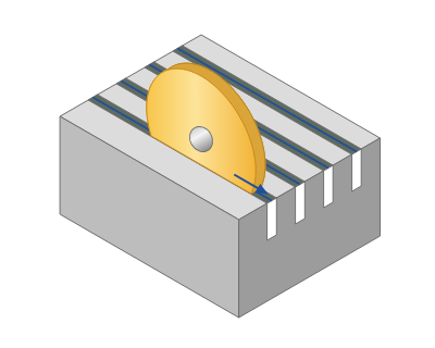
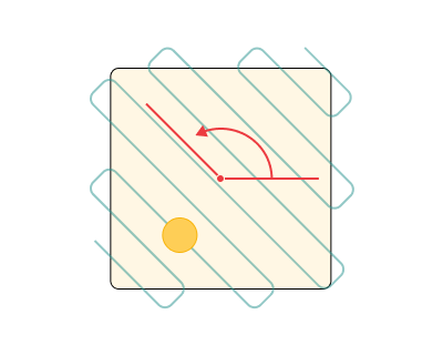
3d. Parallel cuts are generated in a plane.
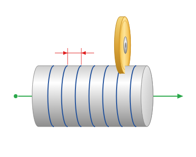
Step. The distance between adjacent cuts (strings). Enter a distance or a percentage of the disc diameter; the default is 20%. If the axial zone is not an exact multiple of the step, the step is reduced to distribute the cuts evenly.
Angle. Sets the cut direction in the plane, measured from the X axis. Available only for 3d.
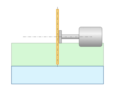
Change side. Reverses the tool axis and shifts the toolpath point by the disc thickness while preserving the cut position.
Click here to expand...
OFF. The original tool position.
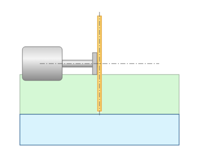
ON. The tool is positioned on the opposite side of the cut.
Roughing:
Defines how material is removed within each cut.
Click here to expand..
By layers. Machining uses separate layers at the specified depth of cut. The shape of the turns relative to the part and workpiece depends on Workpiece.
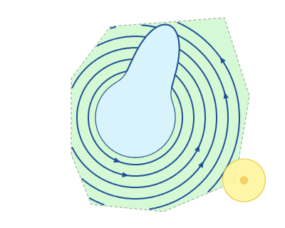
Adaptive. Material is removed along a spiral while limiting the width of cut. Rounding radii control the smoothness of roughing passes, links, and toolpath corners.
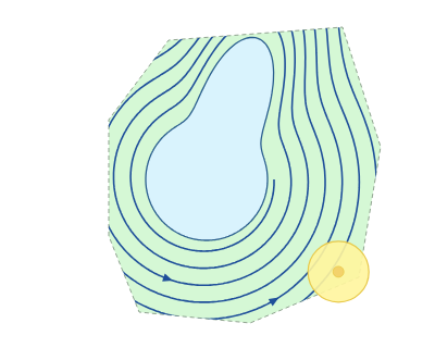
Depth of cut. The distance between adjacent layers within a cut. Enter a distance or a percentage of the disc diameter; the default is 100%.
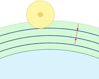
Workpiece. A parameter within Roughing on the Strategy tab. It is available only when Roughing is set to By layers and determines how the turns of each layer are generated relative to the workpiece. With Adaptive, the parameter is hidden and the workpiece is always taken into account.
Click here to expand...
Use workpiece. The default mode. A turn is generated only where workpiece material is present. Where the part rises above the layer, the turn is interrupted. The resulting segments are connected by links with approaches and retracts.
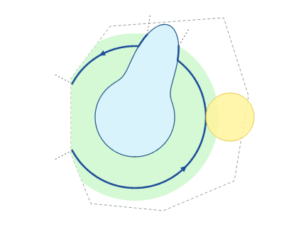
Ignore workpiece. The workpiece and the tool cover are not taken into account when generating turns. Each turn is a continuous pass along its entire length: it follows the layer where the part is lower and the part surface where the part is higher. There are no breaks or retracts within a turn. The layers are limited only by the top machining level, rather than the top of the workpiece, so some turns may pass through empty space.
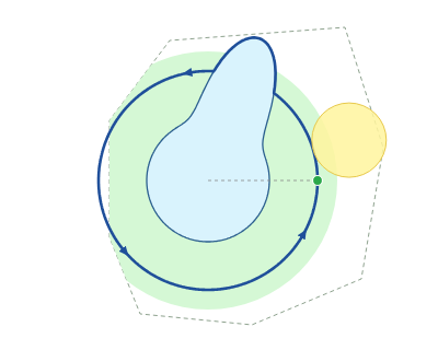
Link feed outside. The turns are continuous, as in Ignore workpiece mode. Where no workpiece material is present, the tool moves at the short link feed; within the material, it moves at the working feed. Only the feed changes at the material boundary, without a retract. In the illustration, blue lines indicate the working feed and the orange dashed line indicates the short link feed.
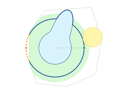
Minimum cut depth. A parameter within Roughing, available only when Workpiece is set to Ignore workpiece or Link feed outside. The default value is 0.1 mm. The cut depth of a turn is the distance from the top of its layer to the lowest point of the part along that turn. Turns with a cut depth below the specified value are not generated. This removes lower turns that follow the part surface almost entirely and remove very little material. A value of 0 allows all turns to be generated.
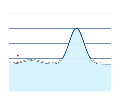
The following parameters are available only with Adaptive roughing.
Corners smoothing. The radius used to smooth toolpath corners near the part surface.
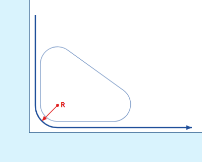
Rough rounding radius. The rounding radius for roughing passes.
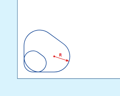
Linking radius. The radius of arcs connecting the passes. It must be at least the safe distance; the inspector marks an invalid value as an error.
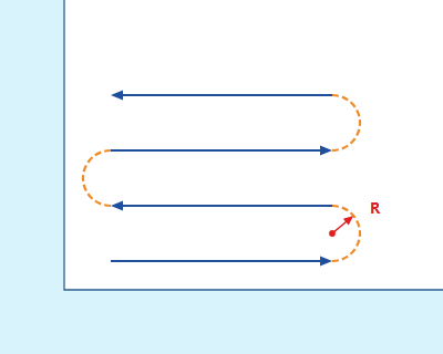
Job zone:
Limits machining along the rotary axis and within an angular range. Available only for Rotary machining.
Click here to expand..
Rotary axis. Set the axis in the inspector or with the mouse. Orientation follows X, Y, or Z of the base coordinate system, or a custom direction; Origin defines the axis position. Base CS is Global CS or WCS.
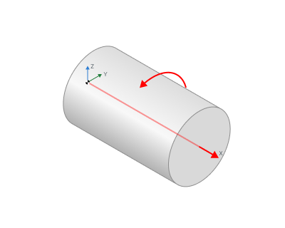
Min. axial position. The lower axial limit: Auto or a value measured from the rotary axis origin.
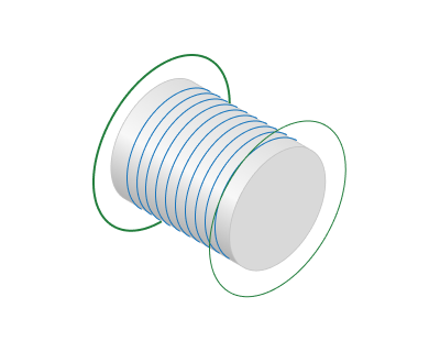
Max. axial position. The upper axial limit: Auto or a value measured from the rotary axis origin.
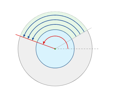
Angular domain. Selects a full revolution or a sector between the start and finish angles. Adjust the limits by dragging or entering a value beside the dimension line.
Full circle. Turns extend around the full circle.
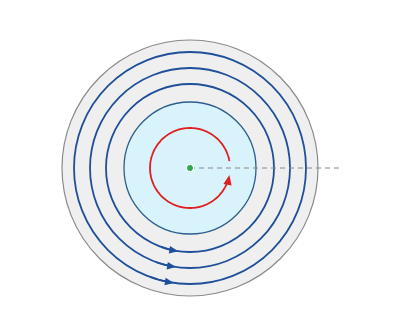
Sector. Turns are limited to the specified angular range.
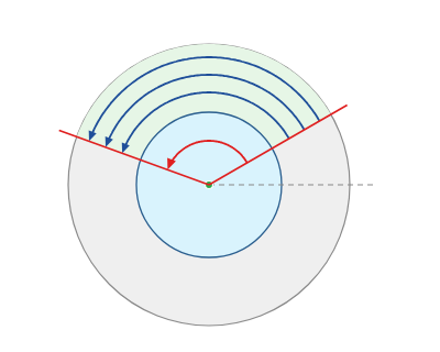
Start angle. The start of the sector, measured from the zero-angle direction.
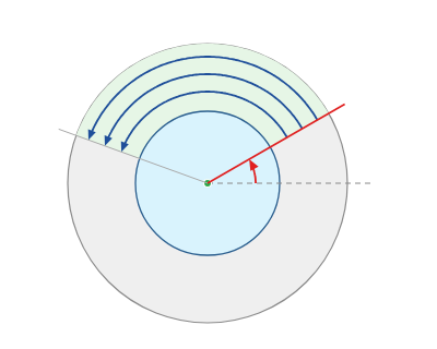
Finish angle. The end of the sector, measured from the zero-angle direction.
Axial direction:
Defines the order of cuts along the axis. Available only for Rotary machining.
Click here to expand..
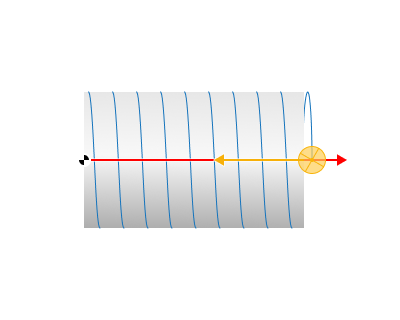
Forward. From the minimum to the maximum axial position, in the rotary axis direction.
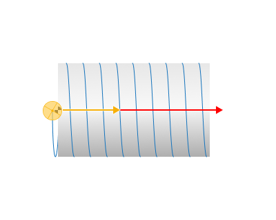
Backward. From the maximum to the minimum axial position.
Milling type:
Click here to expand..
Climb. The feed follows the cutting edge motion at the contact zone.
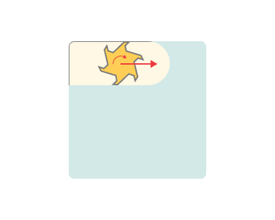
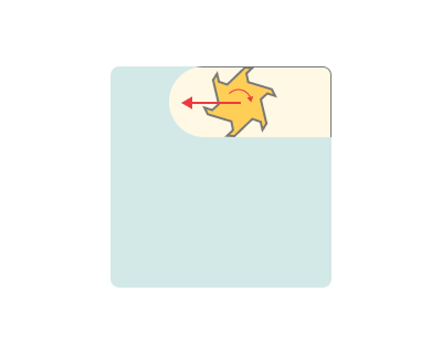
Conventional. The feed opposes the cutting edge motion at the contact zone.
Both. Allows both machining directions.
Sorting:
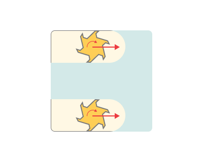
Toolpath uniting mode defines the order in which strings and layers are machined.
Click here to expand..
By layers. Each cut is machined to its full depth before the next cut is started.
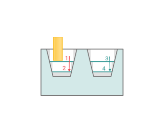
By strings. One layer is machined across all cuts before the next layer is started. Within a layer, machining proceeds region by region, completing one region before moving to the next.
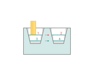
With Link feed outside, the layer is not split into regions: the turn remains continuous.
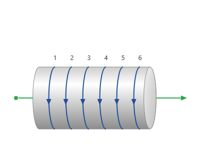
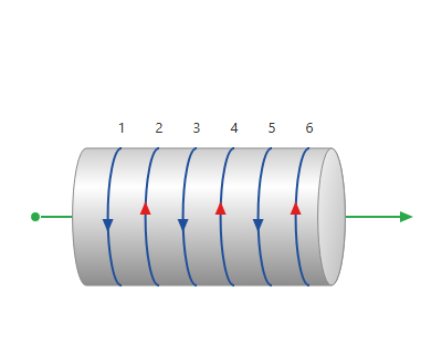
Reverse odd strings. Reverses the machining direction of every second cut: the 2nd, 4th, 6th, and so on.
OFF. Adjacent strings follow the same direction.
ON. Adjacent strings alternate direction.
Machining levels:
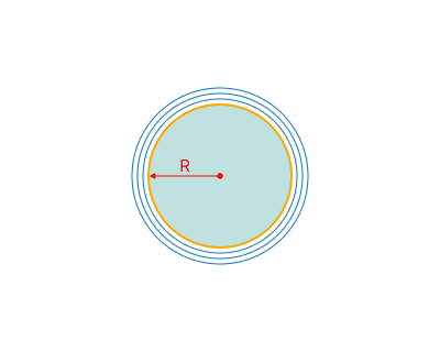
For Rotary machining, levels are distances from the rotary axis, not Z heights.
Click here to expand..
Top level. The upper limit of the machining layers. Available only with By layers roughing.
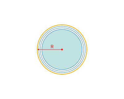
Bottom level. The lower machining limit; no turns are generated below it.
Parameters:
This tab contains the main parameters for controlling the part, workpiece, fixture and other items, which allow you to change the trajectory. Details
Links/Leads:
This tab defines tool approach and return, safe motions, and links between working passes.
Click here to expand..
Consists of:
Approach/Return. Moves from the tool change position to machining and back. Details
Safe motions. The safety surface and safe level for tool movements. Details
Advanced links settings. Rotary axis motion settings for links. Details
Links. Rules for entry and exit links and links between levels and strings. Details
Distances. Distances used by linking rules to switch feeds. Details
Feeds/Speeds:
Sets the spindle speed and feeds for toolpath segments. First pass feed and Return feed are unavailable in this operation. Short link feed is used outside the material with Link feed outside. Details
Transformations:
Coordinate transformations applied to the calculated toolpath. Details
Part:
The part model defines the geometry to machine and is checked for gouges. Details
Workpiece:
The model of the initial material to machine. Details
Fixtures:
Clamping devices and other objects to account for during machining. Details