View control toolbar
Application Area:
Contains tools to manage how objects appear in the graphic window and configure their view. The commands on this panel operate in the same way as in the CAM system. See more.
Toolkit:
Zoom extents.
![]() - When you click the button, the system sets the zoom level to fit all geometric objects in the graphic window.
- When you click the button, the system sets the zoom level to fit all geometric objects in the graphic window.
3D model visualization modes.
![]() - Shade. Displays only the surfaces of the 3D model with shading.
- Shade. Displays only the surfaces of the 3D model with shading.
![]() - Shade plus Wire. Displays both the surfaces and edges of the 3D model.
- Shade plus Wire. Displays both the surfaces and edges of the 3D model.
![]() - Wire. This mode shows only the edges and isolines of 3D bodies and surfaces, with no shading.
- Wire. This mode shows only the edges and isolines of 3D bodies and surfaces, with no shading.
Ambient Occlusion. It is a shading and rendering technique used to calculate how exposed each point in a scene is to ambient lighting .
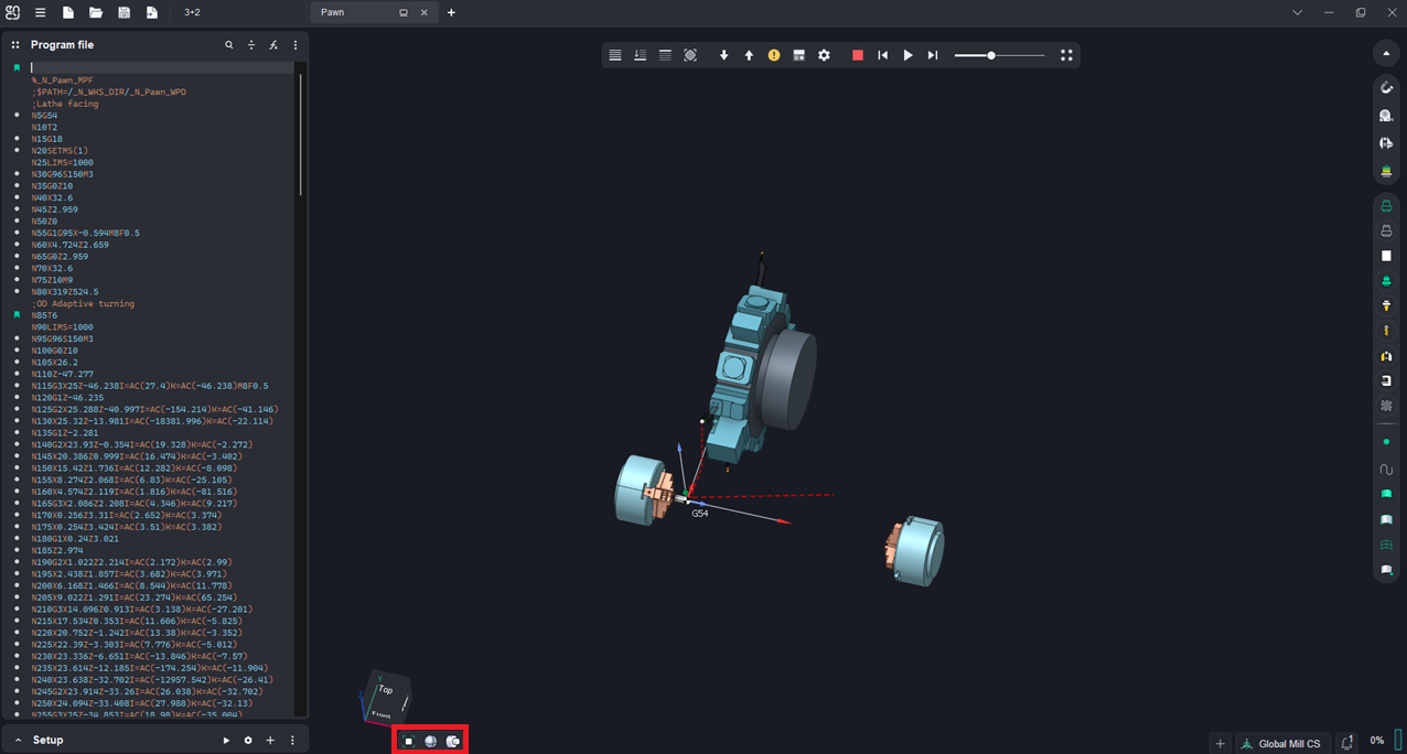
Rotational body visualization modes.
Handles the display of 3D models in lathe projects.
![]() - 3D. Displays the external view of the 3D model.
- 3D. Displays the external view of the 3D model.
![]() - 3/4. The 3D model is sectioned to remove a quadrant with the part axis, leaving the rest visible.
- 3/4. The 3D model is sectioned to remove a quadrant with the part axis, leaving the rest visible.
![]() - 1/2. Half of the 3D model, sliced along its axis, is displayed.
- 1/2. Half of the 3D model, sliced along its axis, is displayed.
![]() - 2D - Shows a flat section of a part.
- 2D - Shows a flat section of a part.
Section plane.
![]() - This button enables (or disables) a special mode for displaying the internal structure of an object. When turned on, an infinite plane is created, at the intersection with which the cut-off part is marked with bar lines. This feature wors the same way as in the CAM-system. See more.
- This button enables (or disables) a special mode for displaying the internal structure of an object. When turned on, an infinite plane is created, at the intersection with which the cut-off part is marked with bar lines. This feature wors the same way as in the CAM-system. See more.