Visibility control toolbar
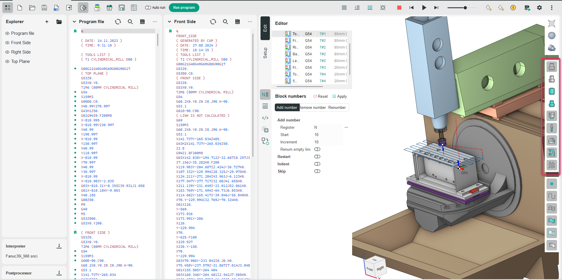
Application area:
The visibility panel is aimed to manage visibility and visualization parameters of objects for different working modes individually (Edit, Setup). The commands on this panel operate in the same way as in the CAM system. See more.
Objects Visibility:
The panel contains buttons to control visibility of:
Geometrical model. Displays the 3D model loaded into the system via the Faces option on the Part tab of the Main Panel. See more.
Part. Displays the object selected as the Part on the Part tab of the Main Panel. See more.
Workpiece. Shows the workpiece associated with this operation.
Machining result. Shows the outcome of the processing for this operation. See more.
Tool holder. Displays the tool holder used in this operation. See more.
Tool. Shows the cutting tool applied for this operation. See more.
Fixtures. Shows the fixture used in this operation. See more.
Machine. Displays the equipment.
Tool path. Shows the trajectories of this node in the technological process tree.
Pressing the left mouse button switches visibility on or off for the corresponding object.
Context Commands:
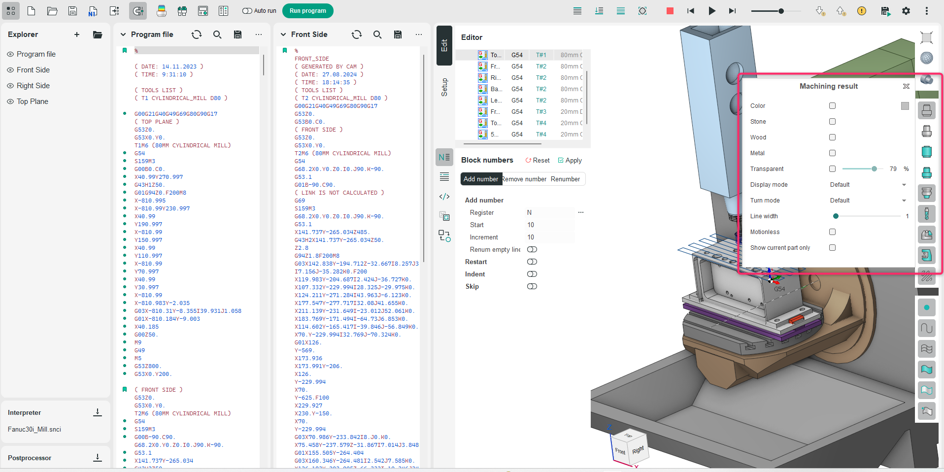
The right mouse button click on the same button opens a pop-up menu to change visualization properties of the object.
The pop-up menu can contain the following items (vary depend on item type):
Color. Switches how to draw the object: by one selected color or by different colors (subject to the tool trace for simulation for example). Click to colored box to select color.
Transparent. The object will be drawn as transparent if the option is selected but as solid otherwise. The transparence extent can be defined in the <Transparence> trackbar.
Metallic. Turns on the metallic reflection for the object faces.
Wood. Turns on the woody reflection for the machining result only.
Stone. Turns on the stone reflection for the machining result only.
Display mode. Switches the visualization mode for the object (wire, shade, shade with edges and default) The Default item means that the object drawing mode is associated with the main drawing mode which is set by the ![]() buttons on the Visualization control toolbar.
buttons on the Visualization control toolbar.
Turn mode. Switches the drawing method for revolution bodies of the object (3D, 3/4, 1/2, 2D and default). The Default item means that the object drawing mode is associated with the main drawing mode which is set by the ![]() button on the Visualization control toolbar.
button on the Visualization control toolbar.
Line width. Defines the width of the line to paint edges and lines of exact object.
Motionless. In the simulation, the object marked as votionless will remain fixed during the process. For example, if the Part is declared stationary, it will appear static during the simulation, while the machine components will perform the relative movements.
Show current part only. In multi-part projects, the machining result will only be shown for the selected (active) part. For Machining Result only.
Show points. For Toolpath only. Allows to visualize points at the end of each toolpath block.
Machine interactive. For the Machine button only. It provides the ability to interactive control the machine nodes and change its visualization parameters.
Change machine nodes. The Machine visual properties dialog will appear where you can setup visual settings for each machine node individually.
Snap to machine nodes. When Smart Snap is enabled, the cursor will snap not only to geometric objects but also to the machine geometry in applicable procedures. For Machine only.
Show normals. Lines aligned with the tool axis will appear at the specified points on the trajectory lines. For Toolpath only.
Show points. Reference points will appear on the trajectory lines. For Toolpath only.