3D contouring
Application area:
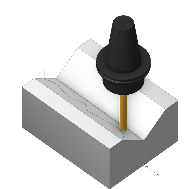
This operation is designed for performing machining along any spatial curves. Machining is performed in a series of 3D passes of the tool. The passes are created offset in Z from each other based on the Z step value. The number of passes and their Z displacement value depends on the machining levels and the step value entered on the parameters page.
Setup:
The Setup tab is used to configure the primary parameters of the project. This can involve the positioning of the part on the equipment, the coordinate system of the part, and more. See more
Job assignment:
Curve. Set work order along curve . See more
Add tabs. Adds tabs along the contour. See more
Properties. Displays the properties of an element. It is possible to add the stock. You can also call this menu by double clicking on an item in the list.
Delete. Removes an item from the list
Restrictions. It allows you to restrict areas that should not be machined. See more
Strategy:
The main parameters of the operation Strategy are described in the 2D contour section. See more
Feeds/Speeds:
Using this dialogue the user can define the spindle rotation speed; the rapid feed value and the feed values for different areas of the toolpath. Spindle rotation speed can be defined as either the rotations per minute or the cutting speed. The defining value will be underlined. The second value will be recalculated relative to the defining value, with regard to the tool diameter. See more
Transformations:
Parameter's kit of operation, which allow to execute converting of coordinates for calculated within operation the trajectory of the tool. See more
Part:
A Part is a group of geometrical elements that defines the space to check for gouges. See more
Workpiece:
A workpiece model of an operation defines the material to be machined. See more
Fixtures:
As the Fixtures the fixing aids such as chucks, grips, clamps, etc., and the restriction areas of any other nature are usually specified. See more
See also:
Operations for the 3-axes milling