Impeller Machining
Application Area:
The operation makes the process efficient for five-axis machining of parts such as monocycles and impellers, integrating strategies for generating the most suitable toolpathes for rough machining of monocycles, finishing of blades and hubs, and refinement of fillets. It also provides additional functionalities to avoid collisions with the tool, holder and the blank.
Job Assignment:
Blade Surfaces. It serves to define blade wall surfaces for machining. If blade geometry is not specified, the system generates a toolpath for machining surfaces enclosed between the Hub and the Shroud surfaces. For rough machining, select the surfaces of two adjacent blades. During finishing, the system machines the selected Blade Surfaces. The geometry selection should include blade working surfaces, upper and lower surfaces, and fillets.
Hub Surfaces. I t identifies the axis of rotation and shapes the space between the hub and the shroud for toolpath formation. The hub must be a surface of rotation. For the finishing process, it is enough to pick any hub surface that has a span from the leading edge to the trailing edge of the blade.
Shroud Surfaces. It shapes the space between the hub and the shroud where the toolpath forms and serves as the base curve for certain strategies. It's essential to select surfaces that limit the lateral outline of the impeller.
Properties. Displays the properties of an element. It is possible to add the stock. You can also call this menu by double clicking on an item in the list.
Delete. Removes an item from the list.
Restrictions. It allows you to restrict areas that should not be machined. See more
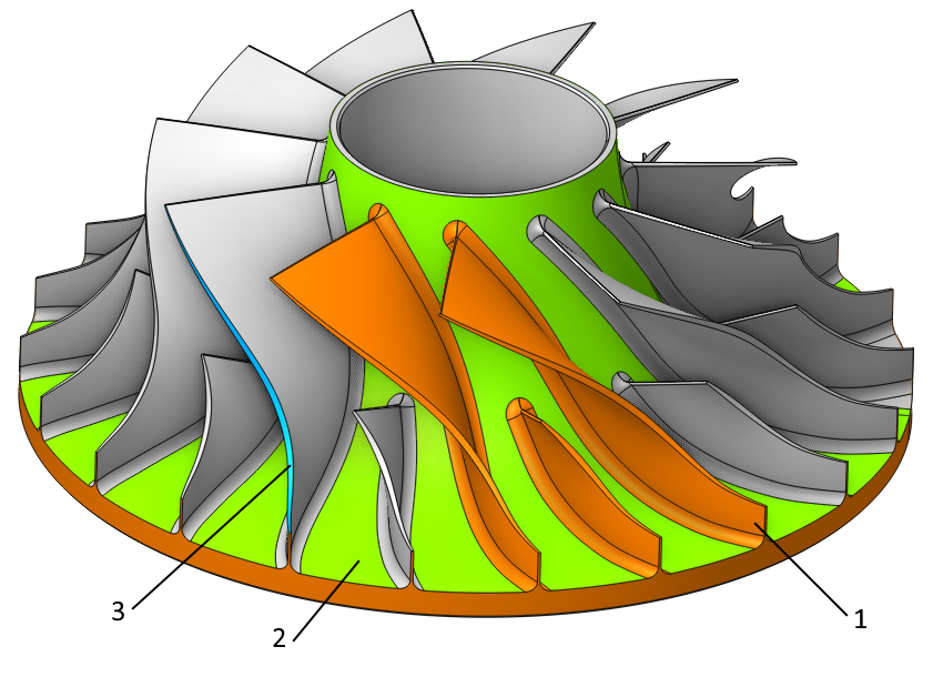
1-Blade Surfaces, 2-Hub Surfaces, 3-Shroud Surfaces.
Strategy:
Machining:
Specify the type of machining and the surface to process.
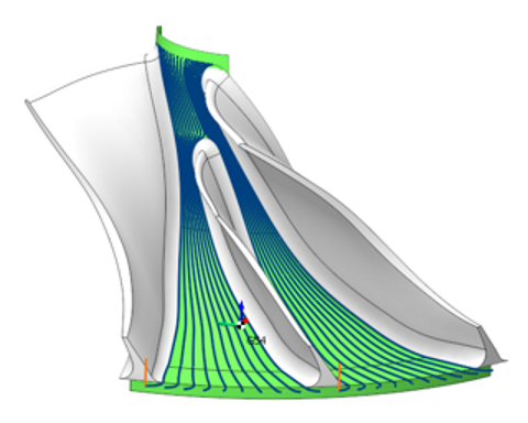
Roughing. Executes rough machining on the impeller blank within the area defined by the Hub Surfaces, Shroud Surfaces, and the two adjacent selected Blade Surfaces.
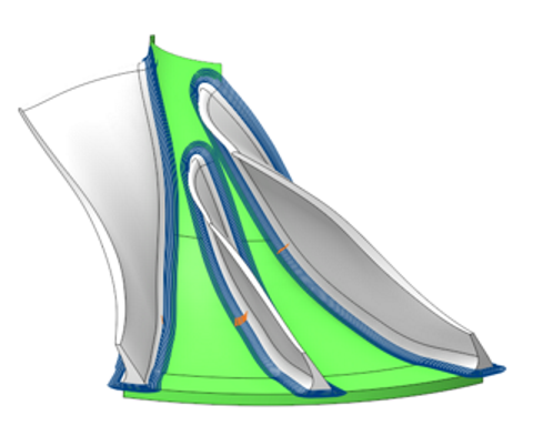
Blade Finishing. Performs finish machining on the selected Blade Surfaces. Set the Hub Surfaces and Shroud Surfaces first. The process will focus only on theselected Blade Surfaces if any are chosen. If none are selected, the machining will cover all the impeller’s blades.
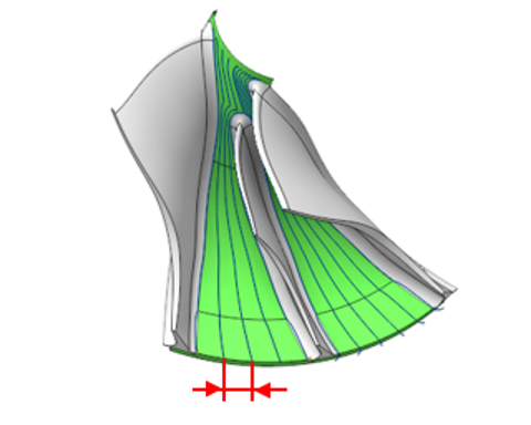
Hub Finishing. Performs finish machining on the selected Hub Surfaces in area between the selected Blade Surfaces.
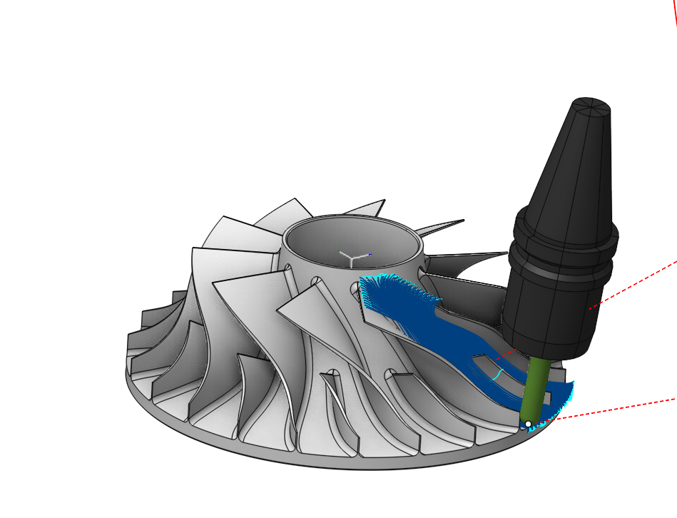
Fillet Finishing. Executes fine machining of the fillet surfaces between the blade and hub. Set the Hub Surfaces and Shroud Surfaces first. The process will focus only on the area of selected Blade Surfaces if any are chosen. If none are selected, the machining will cover all the impeller’s fillet surfaces.
Step. The maximum allowed width of cut .
Depth step. The distance between roughing passes.
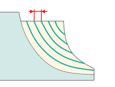
Count. It is the count of passes on the fillet surface when the Fillet Finishing strategy is active. This number of passes extends on each side from the middle of the fillet.
Strategy:
This parameter allows the user to achieve a required toolpath:
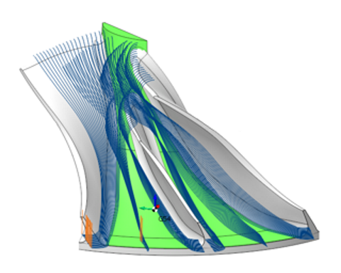
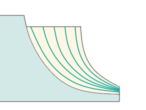
Morph Between Shroud and Hub. The tool paths are the lines that result from a smooth transition from the generating lines of the shrood to those of the hub . They pass through a specified Step (for finishing ) or a Roughing Step (for roughing).
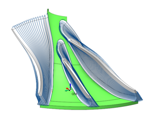
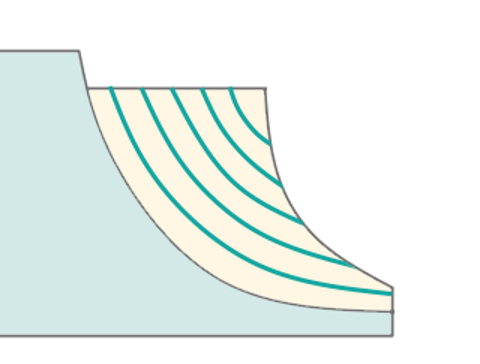
Offset from Hub. The system creates the toolpaths on surfaces that offset the Hub Surfaces by a specified Step for finishing or a Roughing Step for roughing.
Tool Orientation:
Controls tool axis orientation.
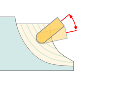
Lead Angle. It is a n additional tool tilt angle within the plane of motion direction.
Avoid Collisions:
With the Check Holder function, this feature detects segments of the toolpath where the tool holder collides with the part and modifies those segments according with the specified strategy. See more.
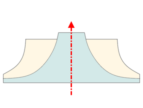
Rotary Axis:
This feature permits the manual designation of the impeller's axis. Select one of the Workpiece CS or Global CS axes, that the impeller's geometric axis should pass through .
Sorting:
Controls the sequence of toolpath passes during the surface machining .
Trim rolls.
The cutter 'rolls' around the sharp outer corners of a model. The tool path is smooth but not always optimal. This parameter works similarly to the Waterline roughing operation. See more
Links/Leads:
In the Links/Leads tab, you define the parameters for rapid movements. These movements include tool approach from the tool change position, engage to the start of the working stroke, retraction after the final cutting motion, transitions between working passes, and return to the tool change point. You can configure the sequence of movements along the coordinates, the trajectory of these motions, and the magnitude of displacements.
Feeds/Speeds:
Using this dialogue the user can define the spindle rotation speed; the rapid feed value and the feed values for different areas of the toolpath. Spindle rotation speed can be defined as either the rotations per minute or the cutting speed. The defining value will be underlined. The second value will be recalculated relative to the defining value, with regard to the tool diameter. See more
Transformations:
Parameter's kit of operation, which allow to execute converting of coordinates for calculated within operation the trajectory of the tool. See more.
Part:
A Part is a group of geometrical elements that defines the space to check for gouges. See more
Workpiece:
A workpiece model of an operation defines the material to be machined. See more
Fixtures:
As the Fixtures the fixing aids such as chucks, grips, clamps, etc., and the restriction areas of any other nature are usually specified. See more