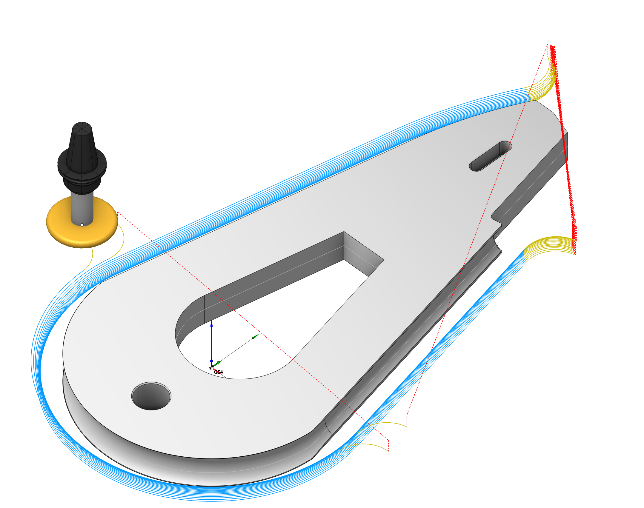
Waterline undercut operation
Application area:
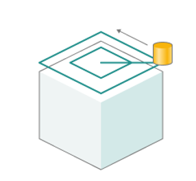
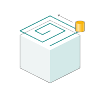
Waterline undercut operation is required for creating recesses, grooves, or cavities using a milling tool. This operation generates a waterline trajectory for undercut tools.
Setup:
The Setup tab is used to configure the primary parameters of the project. This can involve the positioning of the part on the equipment, the coordinate system of the part, and more. See more
Job assignment:
Faces. Select various surfaces of the part as the working task. The system will calculate the trajectory based on the chosen surfaces. See more
Job Zone. Job zones are used to define the part areas that have to be machined by roughing and finishing milling operations. See more
Restrict Zone. In addition to Job Zones in system you can use Restrict Zones to specify the workpiece areas that have not to be machined in the current operation. See more
Top Level. Specifying the top level by model elements. See more
Bottom Level. Specifying the bottom level by model elements. See more
Properties. Displays the properties of an element. It is possible to add the stock. You can also call this menu by double clicking on an item in the list.
Delete. Removes an item from the list.
Restrictions. It allows you to restrict areas that should not be machined. See more
Strategy:
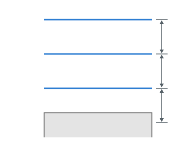
Depth Step.
Material removed in one pass along the tool axis between the Top and Bottom levels.
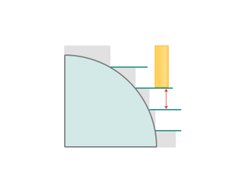
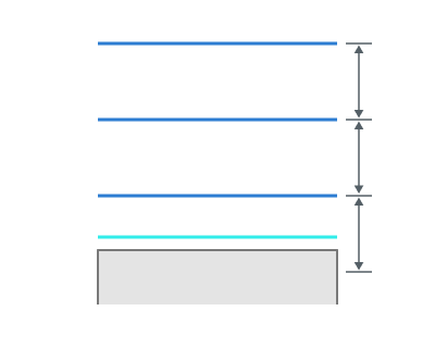
Adaptive step. Additional pass on the upper or lower level. Necessary for cleaning up parts.
Roughing passes.
Toolpath is offset in plane by the 'Roughing step' thickness amount.
Machining strategy:
Equidistant. Processing along curves obtained by offsetting the part contour. See more
Adaptive. The strategy is used to effectively remove large volumes of material with high feedrates, maximal cutting depths (up to the flutes length) and relatively shallow cutting widths (5% to 30% of the tool diameter). See more
Roughing step. Step between roughing passes.
Rough rounding radius. The parameter is necessary for rounding corners during the roughing pass.
Linking radius. Linking radius for the 'links' and also the transitions for the trohoidal arcs.
Step count. Number of roughing passes.
Sorting. This tab is necessary for sorting the displayed passages. This parameter group works similarly to the Waterline roughing operation. See more
Check workpiece. If enabled: It adds the number of passes based on the values of the Roughing step and Step count parameters, taking into account the thickness of the workpiece. If the number of passes exceeds the thickness of the workpiece, the additional passes that do not cut the workpiece are not executed.
If disabled: It adds the number of passes based on the values of the Roughing step and Step count parameters, disregarding the workpiece.
Machining levels.
It defines the range along tool axis for the machining. This parameter group works similarly to the Waterline roughing operation. See more
Milling type.
Сan be assigned in almost all operations, except for the curve machining operations. This allows the user to control the required milling type (climb or conventional) during the toolpath calculation process. This parameter group works similarly to the Waterline roughing operation. See more
Sorting.
Controls the sequence of toolpath passes during the surface machining . This parameter group works similarly to the Waterline finishing operation. See more
Links/Leads:
In the Links/Leads tab, you define the parameters for rapid movements. These movements include tool approach from the tool change position, engage to the start of the working stroke, retraction after the final cutting motion, transitions between working passes, and return to the tool change point. You can configure the sequence of movements along the coordinates, the trajectory of these motions, and the magnitude of displacements.
Feeds/Speeds:
Using this dialogue the user can define the spindle rotation speed; the rapid feed value and the feed values for different areas of the toolpath. Spindle rotation speed can be defined as either the rotations per minute or the cutting speed. The defining value will be underlined. The second value will be recalculated relative to the defining value, with regard to the tool diameter. See more
Transformations:
Parameter's kit of operation, which allow to execute converting of coordinates for calculated within operation the trajectory of the tool. See more
Part:
A Part is a group of geometrical elements that defines the space to check for gouges. See more
Workpiece:
A workpiece model of an operation defines the material to be machined. See more
Fixtures:
As the Fixtures the fixing aids such as chucks, grips, clamps, etc., and the restriction areas of any other nature are usually specified. See more
See also:
Operations for the 3-axes milling