Non-planar slicing
Application area:
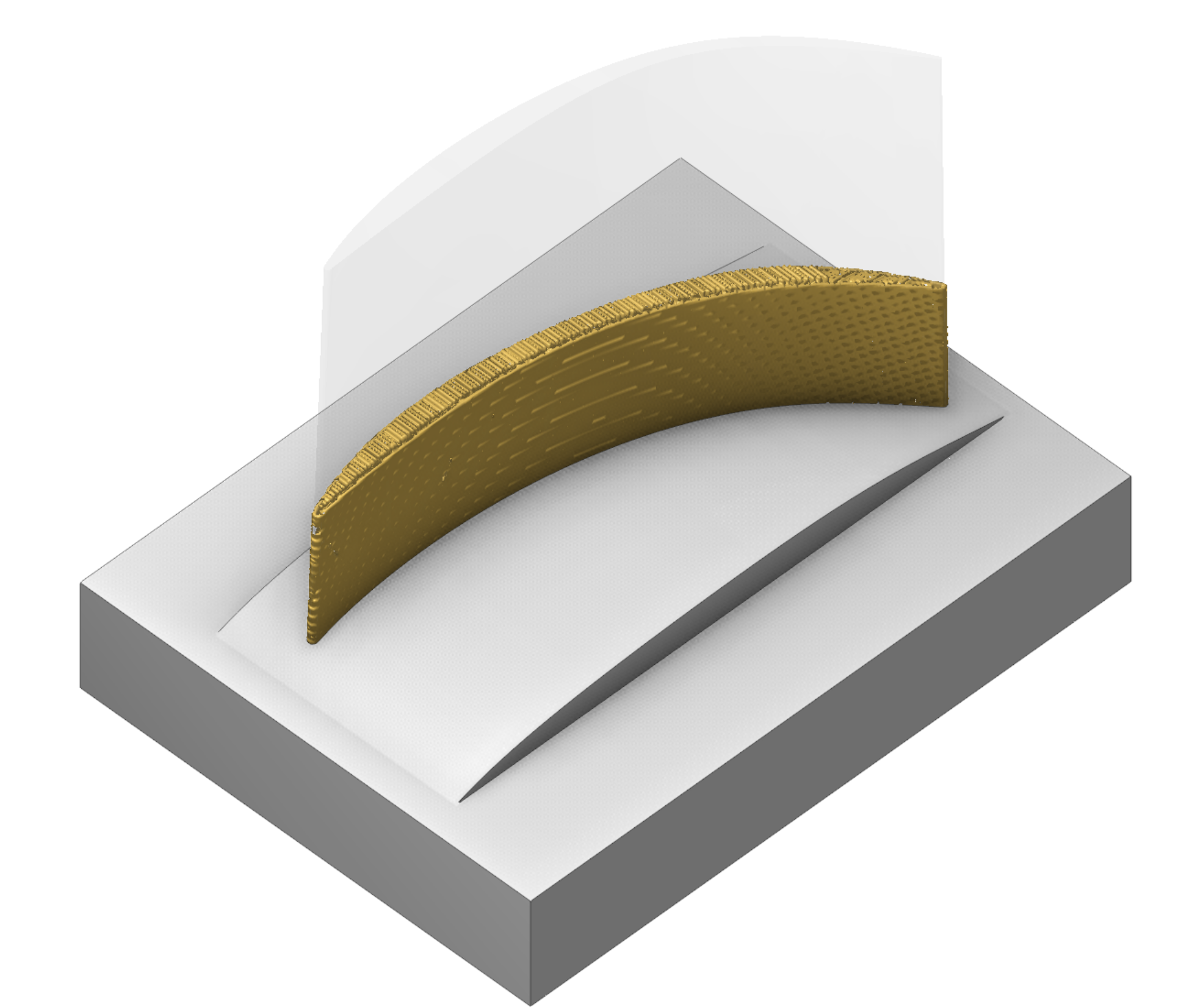
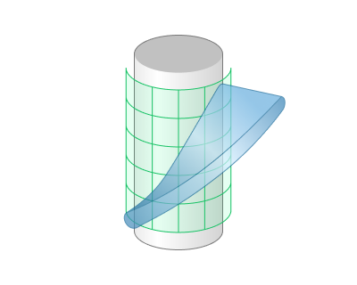
This new operation allows you to print models on arbitrary substrates. It uses a non-planar slicer engine and generates a non-planar additive printing path.
Setup:
The Setup tab is used to configure the primary parameters of the project. This can involve the positioning of the part on the equipment, the coordinate system of the part, and more. See more
Job assignment:
Non-planar substrate. Substrate for printing (for now only mesh file format is supported: .stl, .ply, .amf)
Feature. Desired model, that should be printed (for now only mesh file format is supported: .stl, .ply, .amf)
Properties. Disabled
Delete. Removes an item from the list
Strategy:
Printing strategy.
Defines the printing strategy.
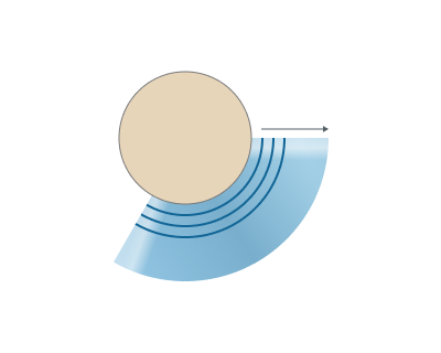
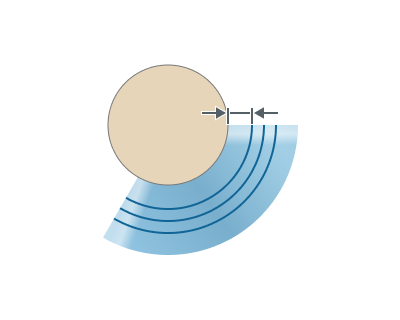
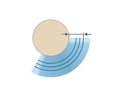
Offset. This strategy performs slicing by offset method from the substrate, which allows to maintain a constant layer height between each layer.
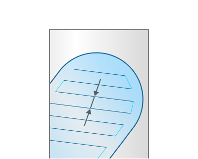
Layer height. Height of each layer in mm. By default corresponds to the working length (WL) of the tool.

Line width. Width of a single line. By default corresponds to the diameter of the tool
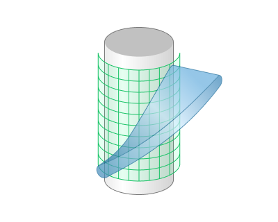
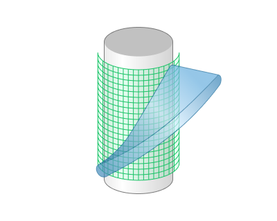
Surface resolution level. Represents the resolution level of the offset surfaces that will be constructed to split the model. Lower values produce faster result, but in lower resolution. Higher values produce slower result, but in higher resolution.

Start offset. The offset value from the substrate, where the printing process will start
End offset. The offset value from the substrate, which represents the finishing boundary of the printing process. However, it may stop earlier depending on the layer height parameter.
Print inner volume.
Offsets the tool path into the model by half of the line width value
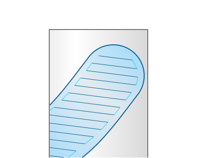
Infill.
A group of parameters to generate an infill for the model.
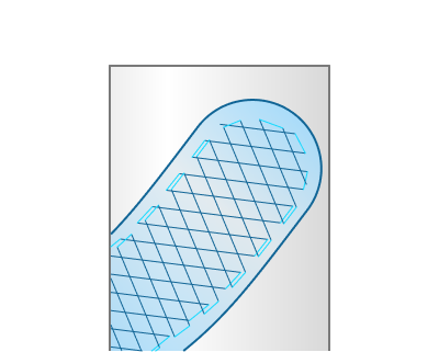
Infill pattern. Defines the infill pattern.
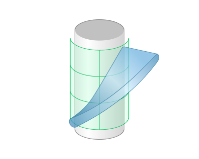
Lines. This infill pattern is created by intersecting non-planar layers with simple vertical planes

Infill orientation. Determines the orientation of the infill in space.
Direction. The direction vector of the infill. By default corresponds to the tool orientation vector.
Tool orientation vector. Tool orientation can be set on a Setup page. See more
Infill density. Adjusts the density of the infill as a percentage.
Alternate lines direction. Alternate lines direction on each layer by 45 degrees
Double walls.
Adds an additional inner wall.
Printing order.
Determines the order of walls and infill when printing.
Parameters:
Output Interpolation.
Using interpolation is one of the main ways to modify the path, allowing you to adjust smoothness and the concentration of points on trajectory. See more.
Corners Control.
This group of parameters allows you to to add some specific behaviour to the toolpath corners. See more.
Transformations:
Parameter's kit of operation, which allow to execute converting of coordinates for calculated within operation the trajectory of the tool. See more