Parts Mode
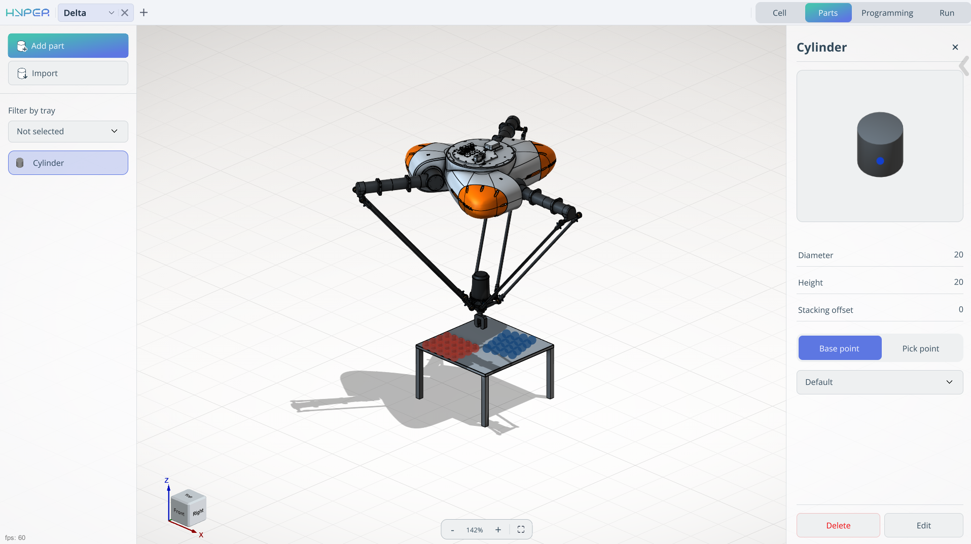
Application Area:
The Part mode allows you to add a model or create it from primitives, as well as place them in the tray.
Import.
It allows you to load a 3D model of the product.
Type. Сylinder, Box, or 3D model.
ustom file. It allows you to reselect the model.
Stacking offset. The parameter determines the vertical alignment relationship between stacked components.
Value = 0: parts are positioned directly atop one another without overlap.
Value > 0: defines the insertion depth for mating parts (e.g., in LEGO‑like interlocking mechanisms, this would equal the height of the connecting cylinder).
Base point/ Pick point. The reference point for placement / The gripping point on the part.
- Unlimited pick and base points can be created.
- Each point supports editing, deletion, and renaming.
- Coordinates can be input manually or selected via model interaction.
- A gripper visualization aids pick point definition, showing the robot’s actual gripping posture.
Name pont. Assigns a name to an existing point
Add/Delete a point. Allows you to create/delete a point that is added to the list of points.
List of points. View point names
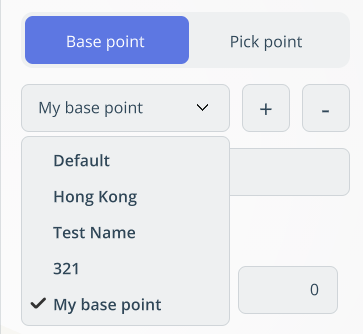
X,Y,Z,Rx,Ry,Rz,A,B,C - Fields for spatial orientation of the point.
Add part.
It allows you to create a model from primitives. In this template, some parameters are identical to those in Import - 3D model.
Сylinder.
Diameter. Distance across the circular base, through the center
Height. Distance between the two bases along the axis
Box.
Width. Defines the width
Depth. Defines the depth
Height. Defines the height
Filter by tray.
It allows you to select a specific tray for work.
List of parts
It displays a list of parts for moving and allows you to edit them.
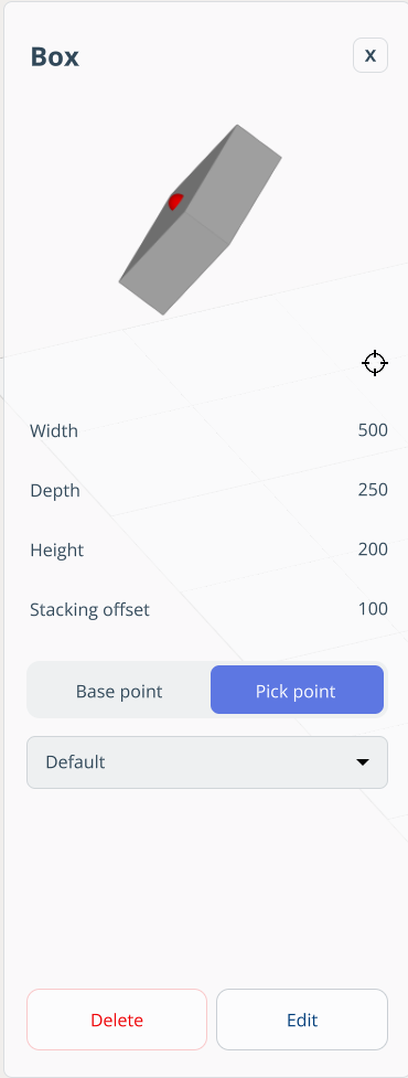
Clicking the part opens a window where you can:
- View model name
- Edit model
- Delete model
- Show base and pick points
- Rotate model (preview)
Work specifics
In this mode, place the parts in their initial positions.
To position the parts in the tray:
- Select the required part in the parts tree.
- In the graphics window, choose the attachment point.
- The selected part will appear in this position.
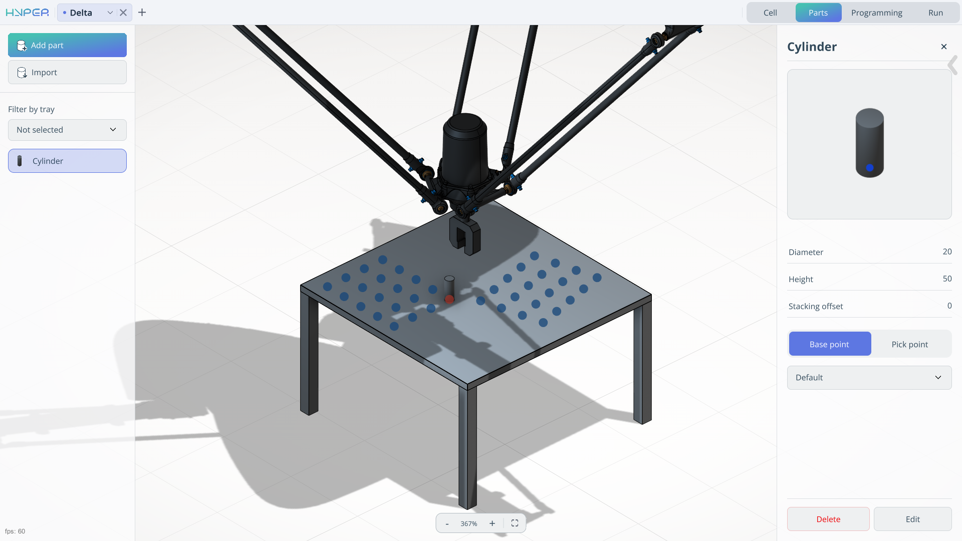
The position where a part is already installed (attachment point) changes its color to indicate that the slot is occupied.
To remove a part from its position, simply click on the attachment point where the part is located.
To add multiple parts at once, press and hold the left mouse button. A dialog box will then appear, prompting you to add this part to the entire tray.
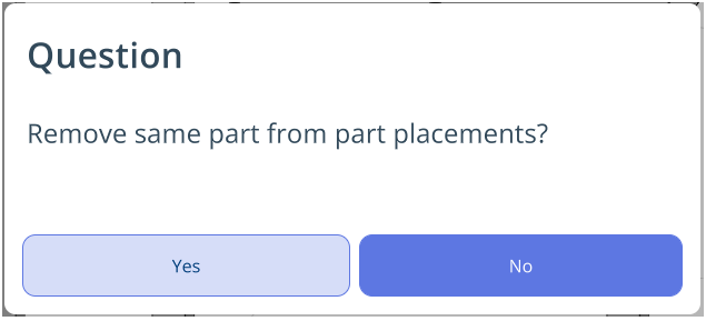
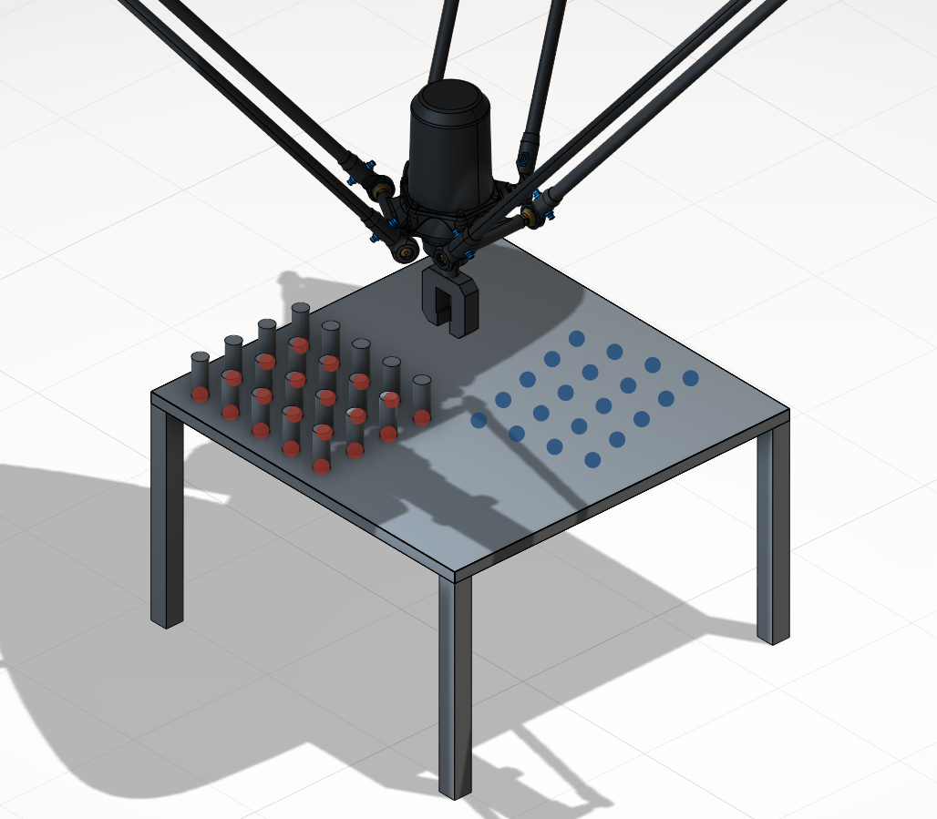
The same mechanism applies to removing parts from the tray.