Application area:
ENCY Hyper is a next‑generation industrial robot programming platform that represents a significant advancement over conventional programming solutions. This document provides a comprehensive overview of the system’s key functionalities, operational modes, and application areas to facilitate efficient onboarding and implementation.
Prior to system deployment, it is essential to thoroughly review the system’s functional capabilities, supported hardware configurations, and underlying programming concepts. Adequate preliminary preparation ensures an optimized implementation timeline, seamless system operation, and minimization of potential operational issues.
ENCY Hyper constitutes a hybrid programming platform that integrates the advantages of both online and offline programming methodologies.
The offline mode enables development and testing of robotic programs within a digital twin environment. This approach allows for comprehensive program verification prior to physical execution, eliminates trial‑and‑error procedures on the production floor, and enhances overall programming accuracy.
The online mode provides real‑time control capabilities that facilitate immediate debugging, dynamic fine‑tuning, and live feedback‑based adjustments to robot behavior.
Compared to conventional offline systems, ENCY Hyper offers several significant improvements: it maintains a continuous connection with the robot, actively monitors program execution, implements immediate operational halt in case of anomaly detection, and ensures maximum safety and reliability standards.
ENCY Hyper has been specifically designed to optimize Pick and Place operations. The platform effectively reduces idle time, improves workflow efficiency, increases automation levels, minimizes manual intervention, and stabilizes production processes.
While optimized for Pick and Place operations, ENCY Hyper demonstrates high adaptability to various industrial applications. The system supports assembly operations, palletizing processes, sorting tasks, quality inspection procedures, milling operations, grinding processes, polishing tasks, painting applications, and welding operations.
Workflow:
1 . Working with ENCY Hyper starts with uploading your equipment from MachineMaker in the special cell file format (.mma) on the Home page. You can prepare the cell yourself or ask your dealer to do it. See more
2. Then your cell will appear on the Home page, where you can open it with a double‑click.
3. In ENCY Hyper, you will need to define trays and part attachment points in Сell mode. See more
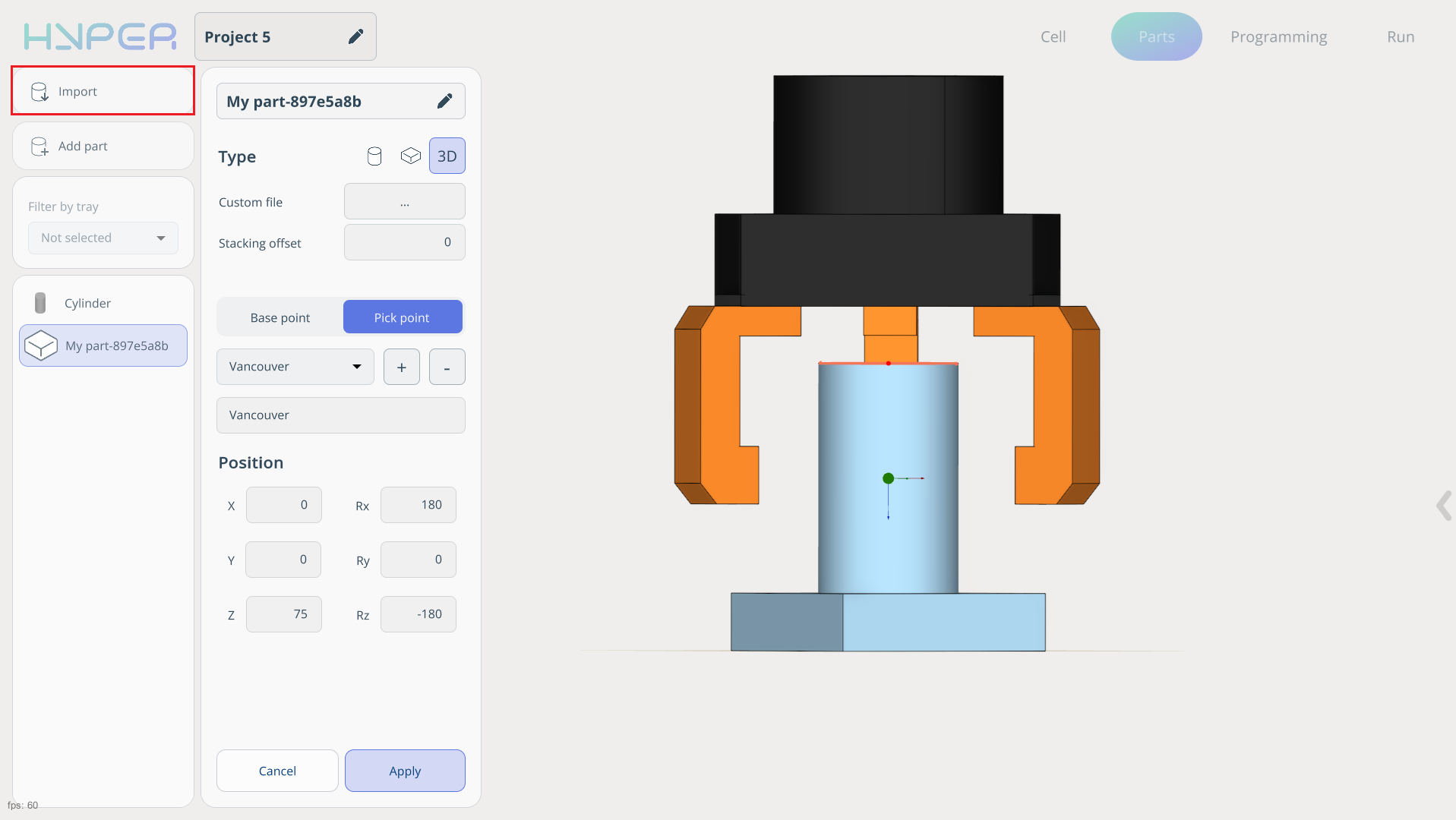
4. In Part mode, you need to upload part models or build them directly in the system using primitives. Also, specify part grip points. See more
5. In Programming Mode, you need to use command blocks to program and calculate the trajectory. See more
6. In Run Mode, you can simulate the resulting trajectory and, with a connected robot, observe its actual operation. See more
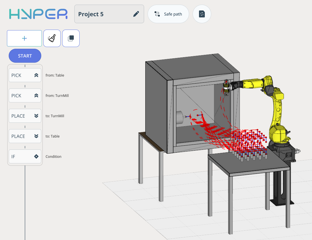
Pick and place (transfer from table to table).
The example shows simple transfer of a part from one table to another.
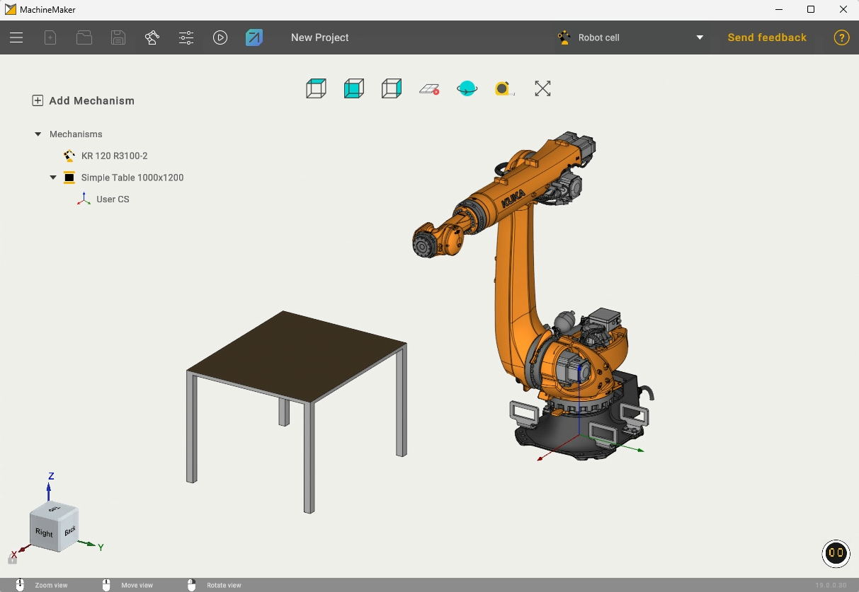
Assembly of a cell for Hybrid can be performed in the MachineMaker application, which is installed together with Hybrid. MachineMaker contains an extensive library of various mechanisms, including robots, movable rails, different tools, and much more.

In this example, we will consider a cell consisting of a robot, a table, and a gripper tool.
To export this cell to Hybrid, click the Hybrid icon at the top of the MachineMaker interface. After that, your project will appear on the start screen.
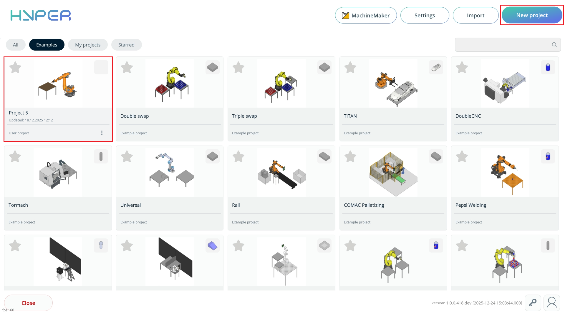
Open your project on the start page using the “Add Project” button. After selecting the project in Windows Explorer, it will appear on the start screen under the All or My Projects tab.
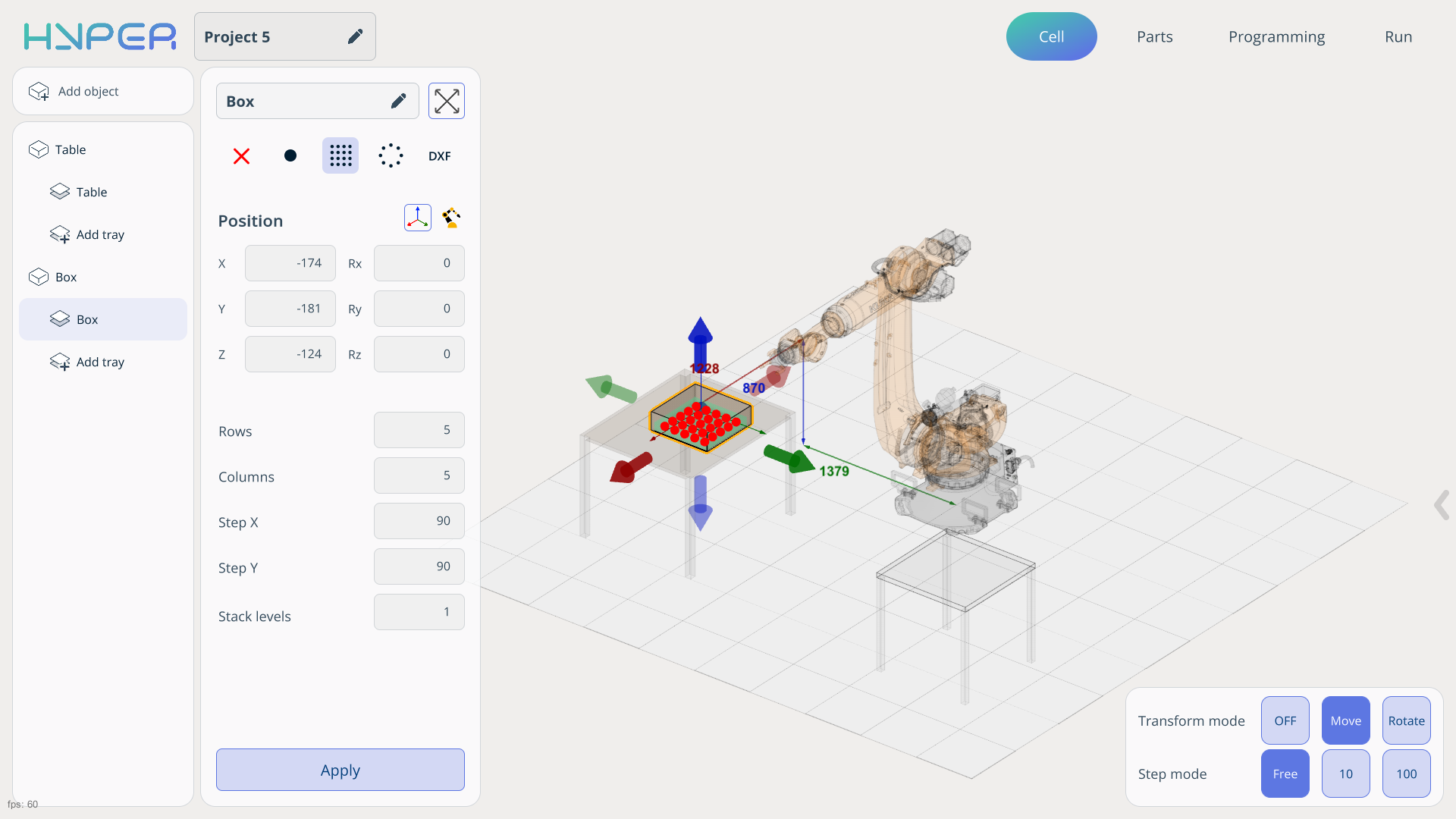
In your project, you can add various objects on the Cell tab. In our example, this will be a table and a custom box into which we will place the parts. See more
On this tab, when adding an object, you can define its dimensions and move it to any required position.
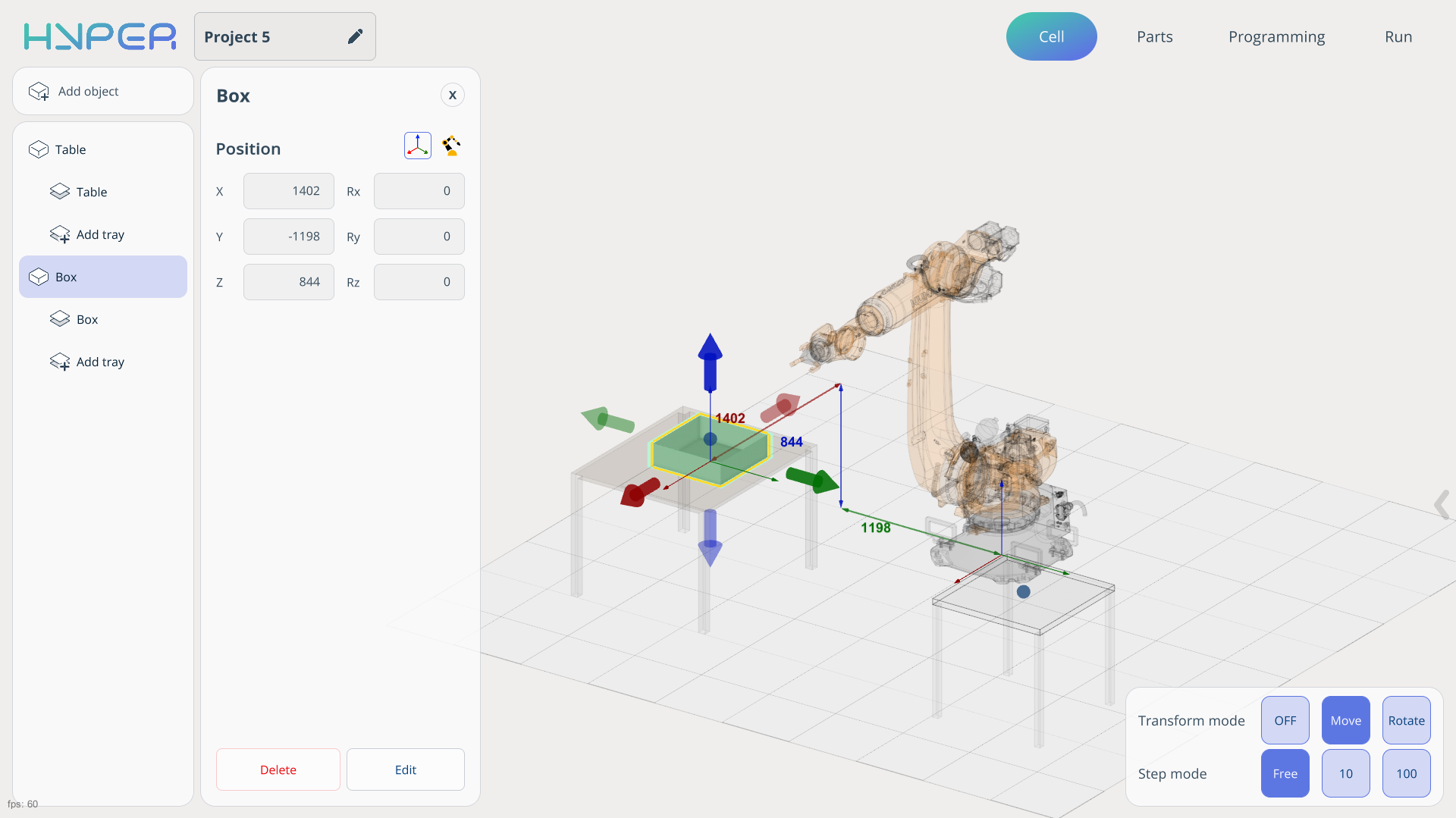
For each object, you can define individual points where the parts will be located. These points can be set either independently or relative to the robot. It is also possible to import predefined positions from your layouts.
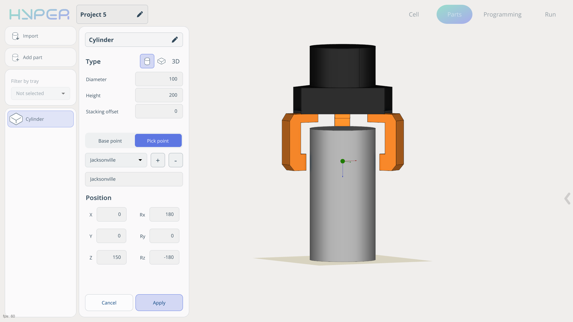
All work related to adding and editing parts is performed on the Parts tab. Parts can be imported or created manually. You can also manually define the Base Point and Pick Point.
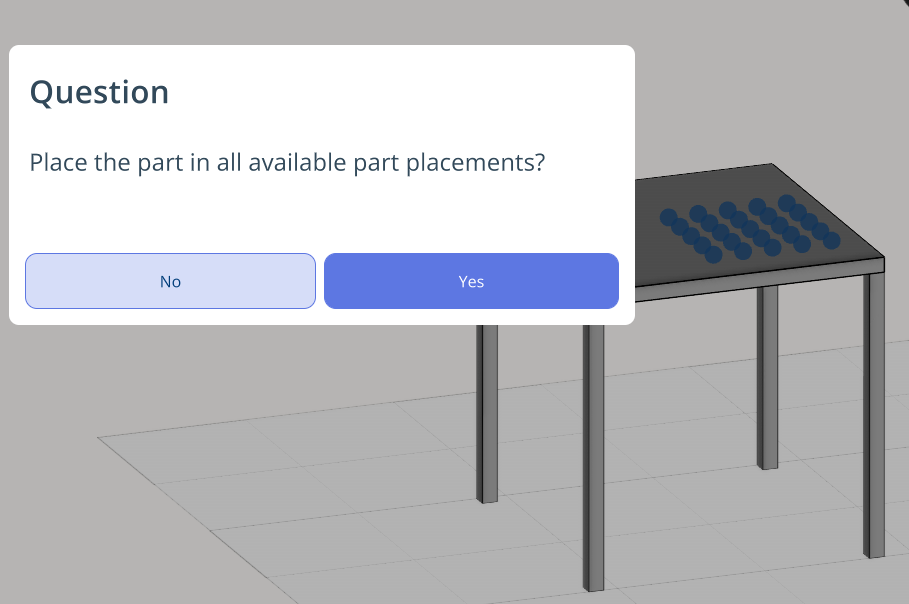
After the parts have been added, they can be placed into the cells created earlier. To avoid adding parts to each cell individually, you can hold the left mouse button and place the parts into all cells at once. See more
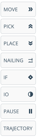
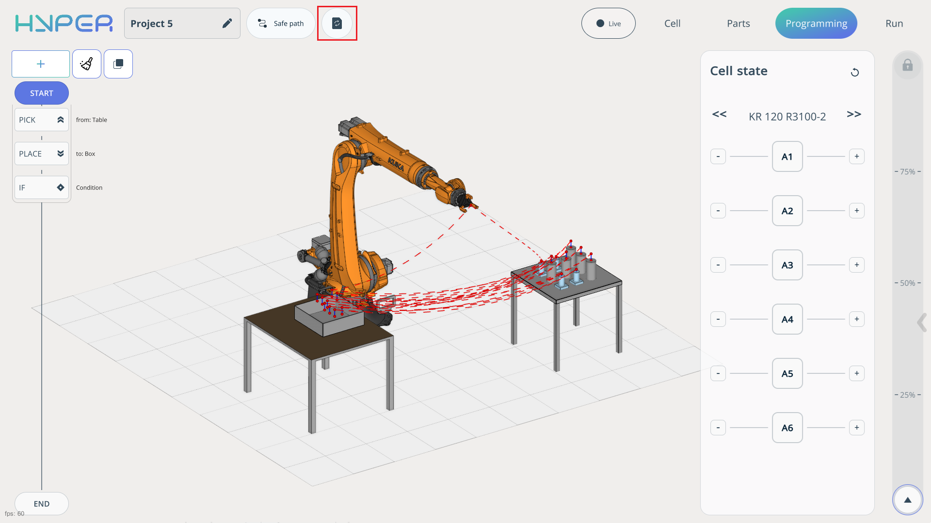
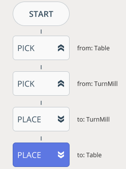
In this example, only the Pick, Place and IF commands will be used. You can find information about the other commands on the corresponding tab.
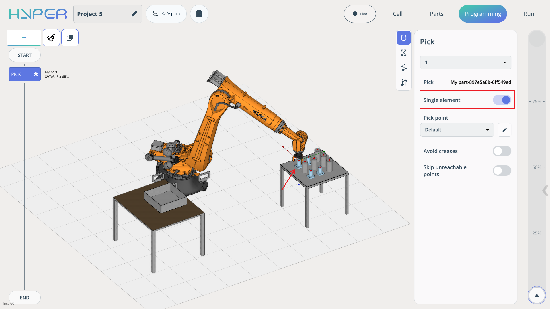
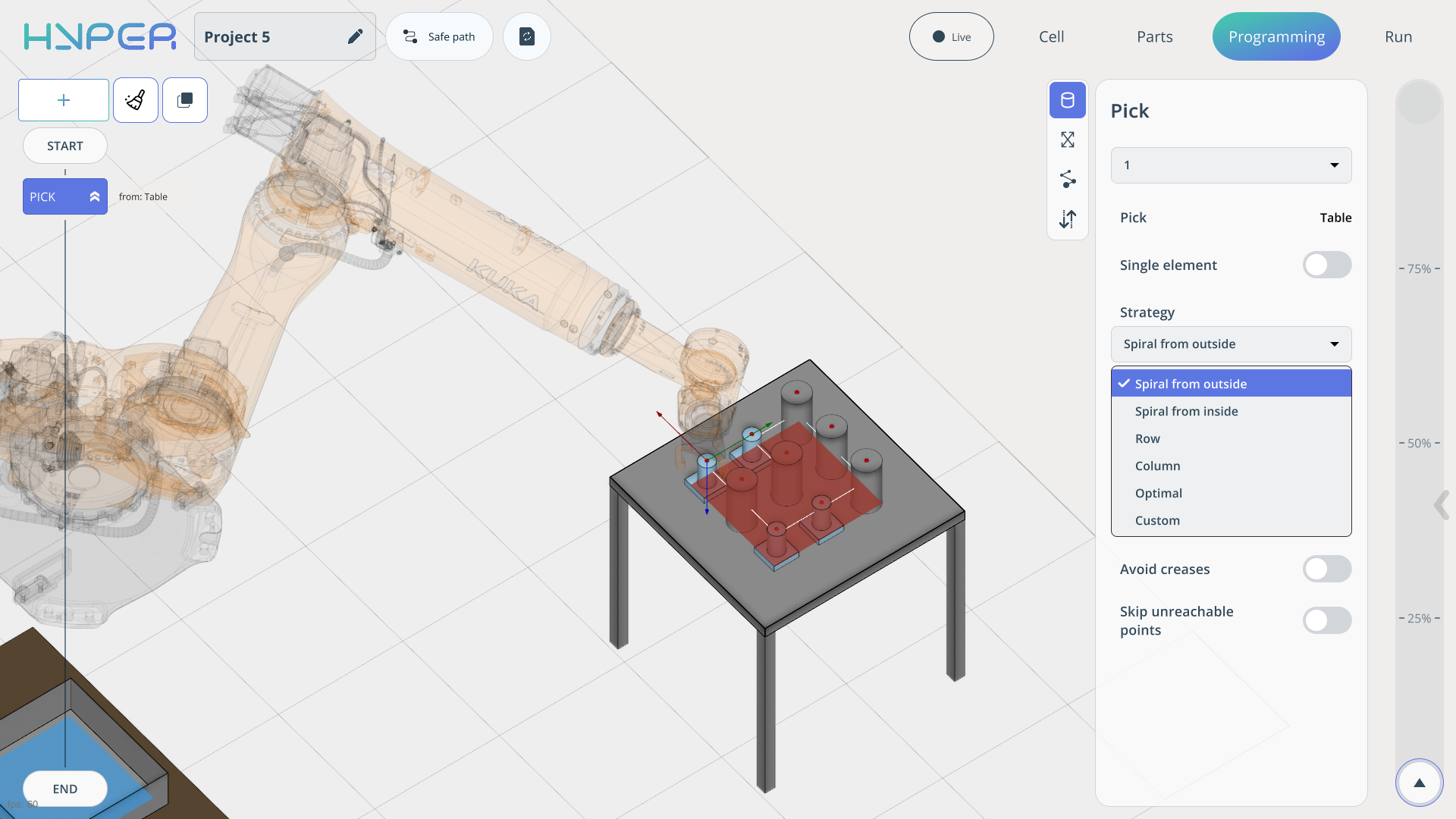
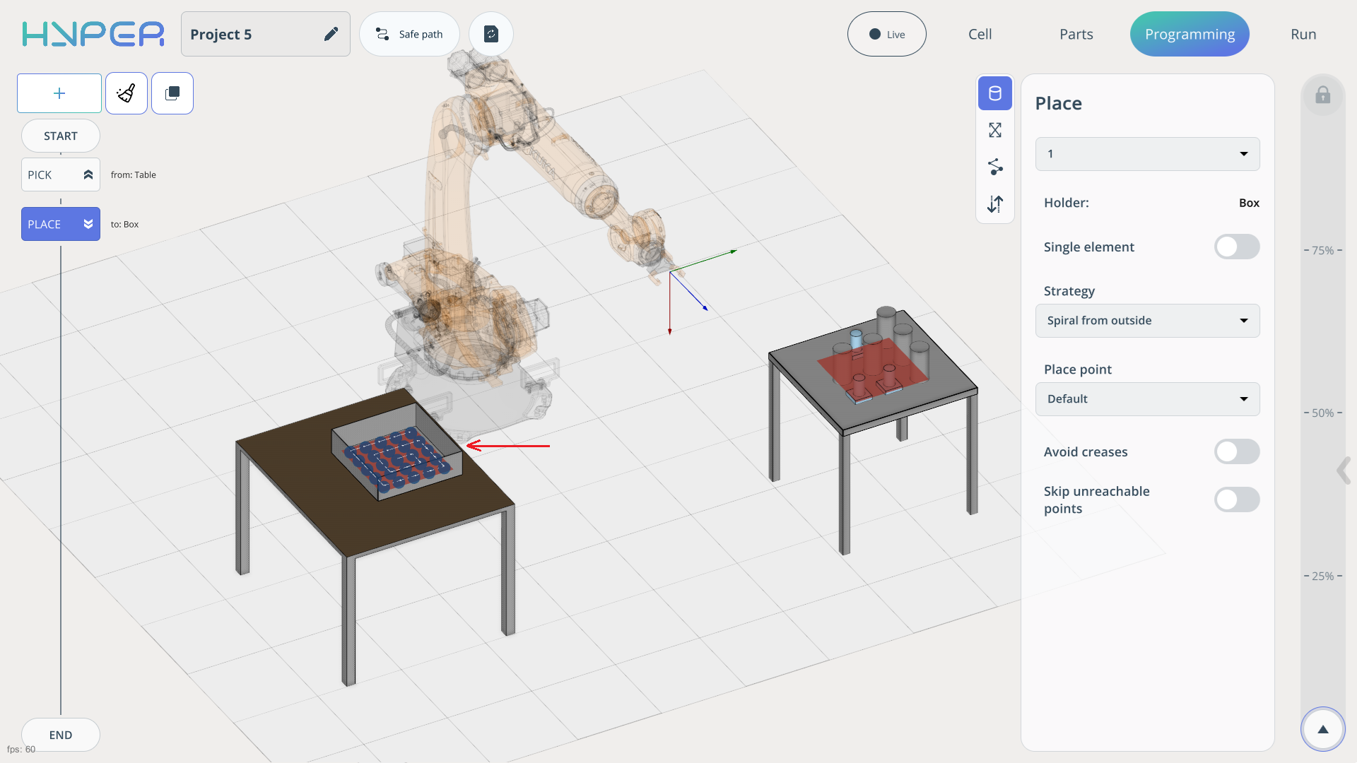
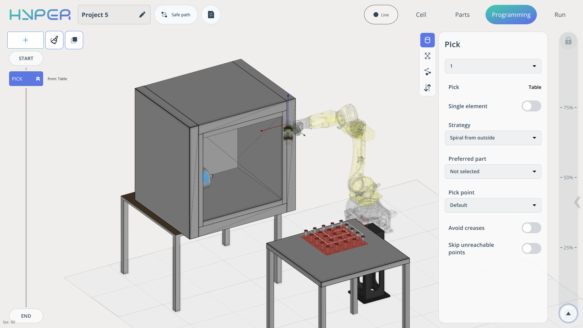
When creating a Pick command, you need to define how the command will be executed. If the slider is set to Single element, the created command will operate on a single part only. If you disable this slider, the program will switch to the entire cell and generate a Pick strategy accordingly.
After adding the command, you can specify which part the robot should start with and define your own Pick point position in the settings.
The strategy can be configured manually by selecting the Custom mode. In all other cases, the program automatically applies its optimized strategies.
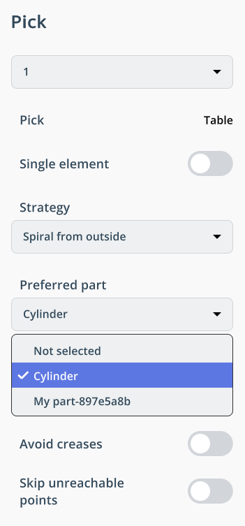
Additionally, when using different parts, the Preferred Part parameter allows you to select which part the robot will work with.
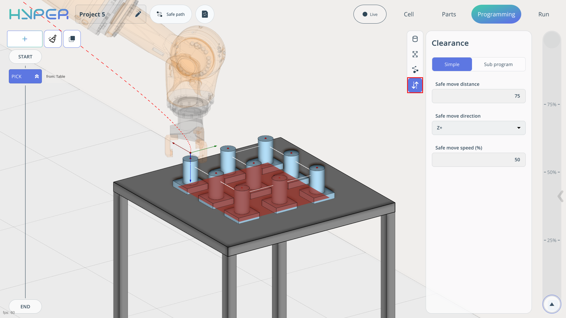
In some commands, you can configure Clearance. This parameter has two modes:
Simple. Allows setting the safe move distance, safe move direction, and safe move speed.
Sub Program. In this mode, Clearance is configured by adding Move, Pause, and IO commands.
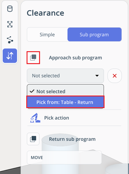
The Sub Program consists of an Approach Sub Program and a Return Sub Program, separated by the Pick action. Various commands can be added to each to achieve more refined robot operation in Pick and Place commands.
To add commands to the Sub Program, use the standard command addition method.
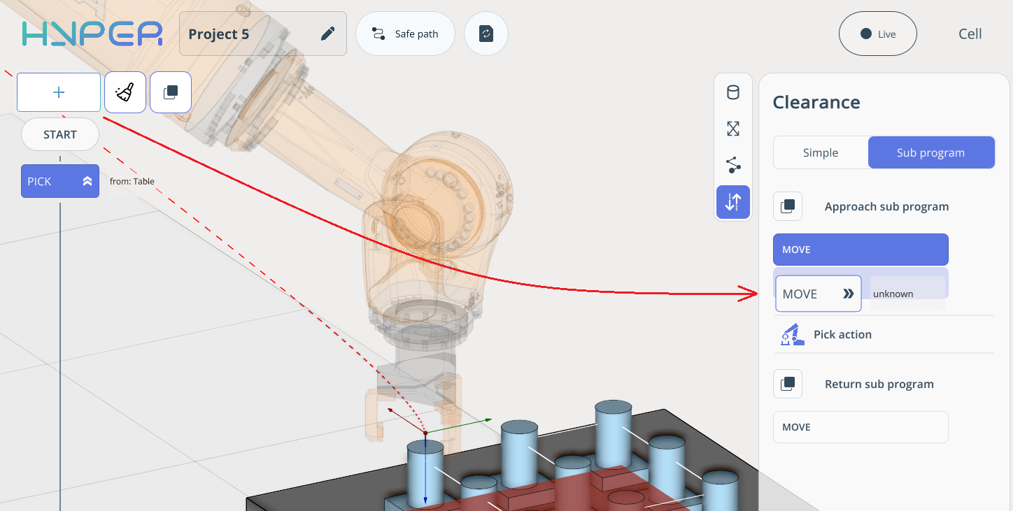
If you have a large Sub Program and need to use the same one in another command, you can load it at any time using the Load Command button in the Sub Program.
For the Place command, simply select the target cell using the left mouse button where the parts will be placed.
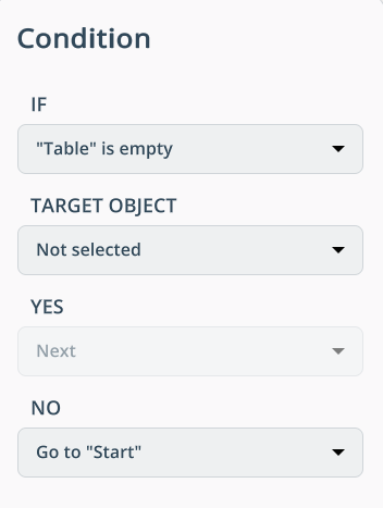
The IF command allows the program to loop the preceding commands and properly terminate them. In this case, we specify that if all parts have been removed from the table, the robot returns to its Home position.
When your program is ready, you need to calculate it before starting the simulation. Use the Recalculate button for this. You will visually see the trajectory along which your robot will move the parts.
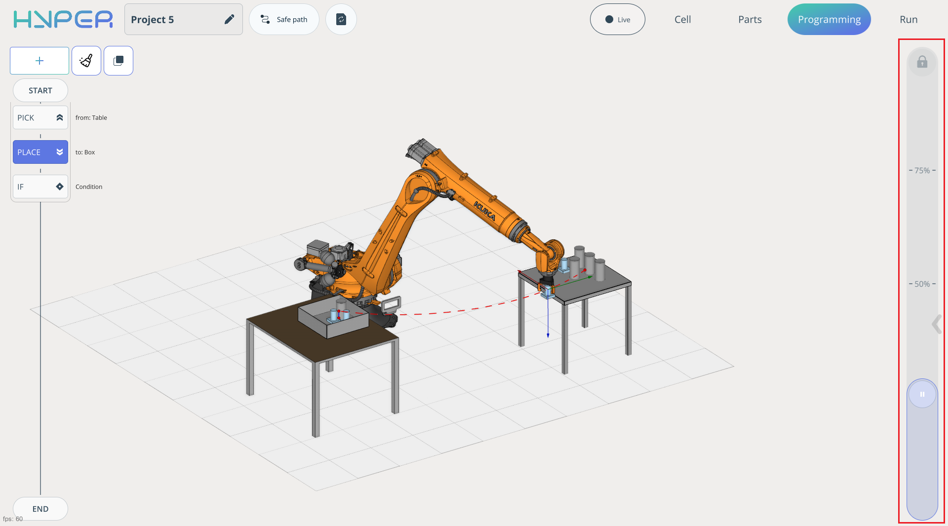
The simulation start slider, which also serves as the speed slider, is located on the left side of the screen. The percentages indicated on the slider represent the speed at which your program simulation will run.
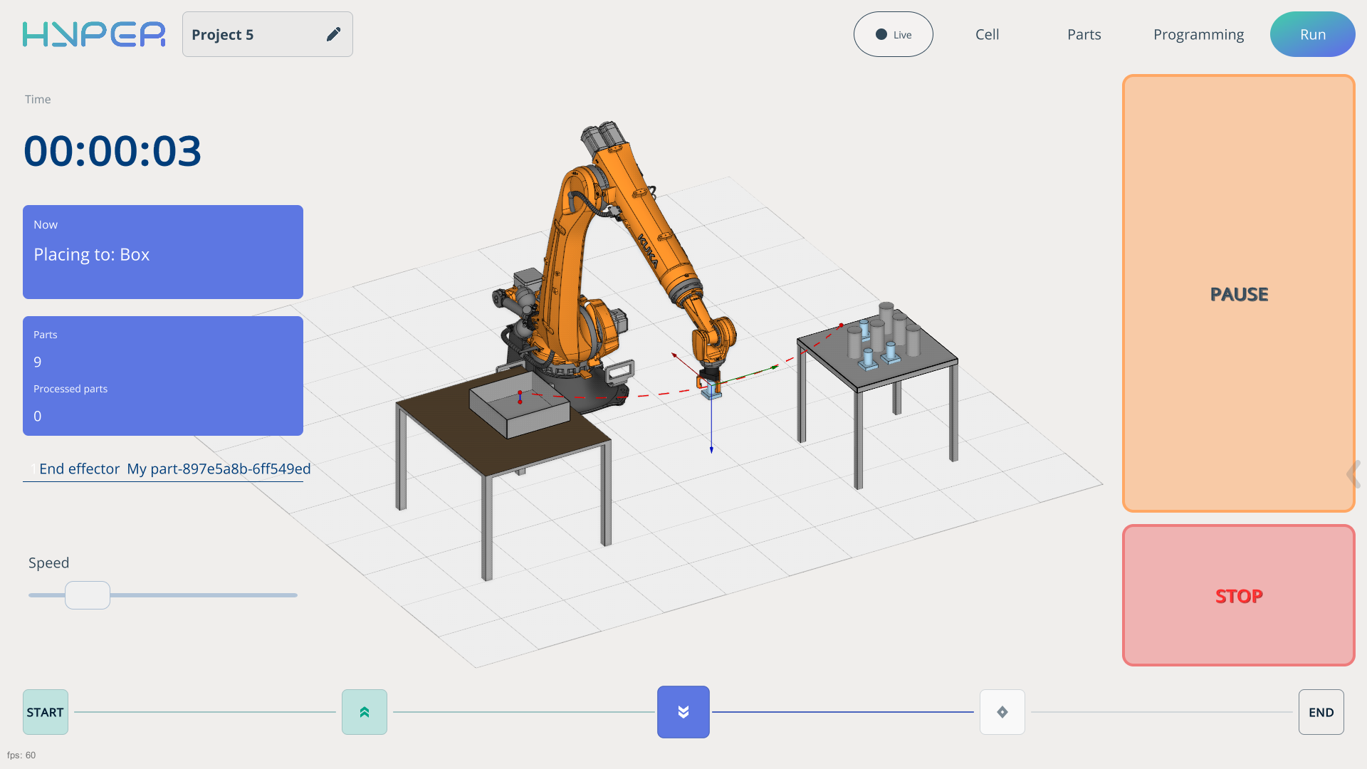
The Run tab is responsible for launching the already generated robot program.
To start the simulation, press the Start button and adjust the speed slider. See more
Pick and place (transfer of the part from the workbench to the machine and back.).
Example of part loading/unloading onto machine.
First, import the project on the Start Page. See more
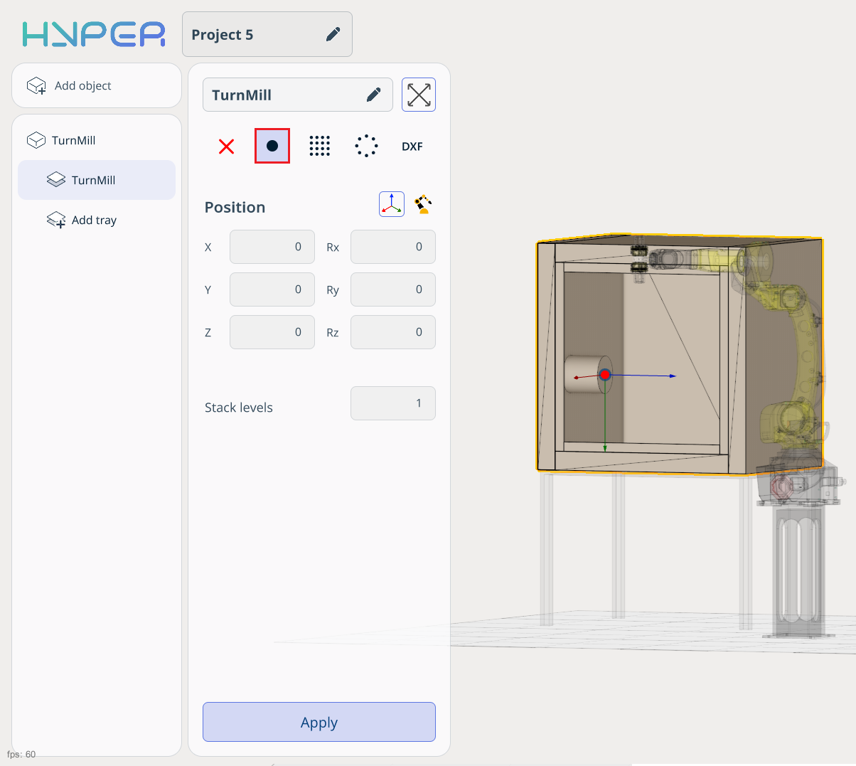
After loading the project, open it and add an object representing a CNC machine.
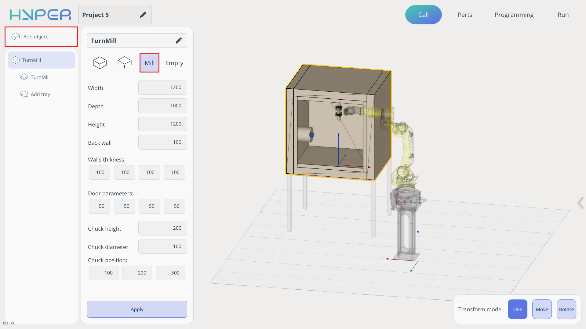
Add a cell for part processing on the machine surface.
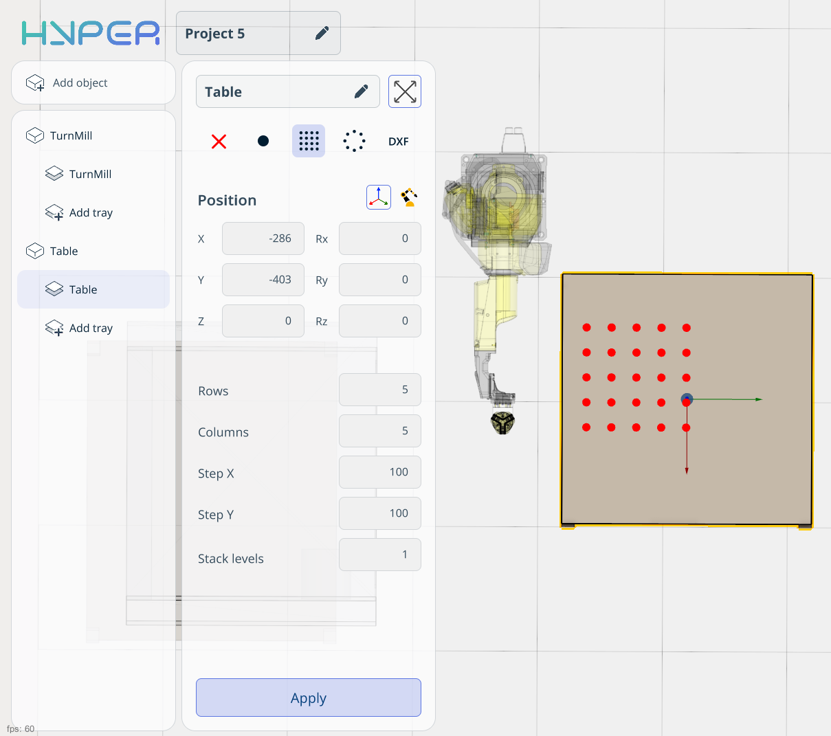
Add a table where the parts will be stored. Add and configure the cell parameters for the table.
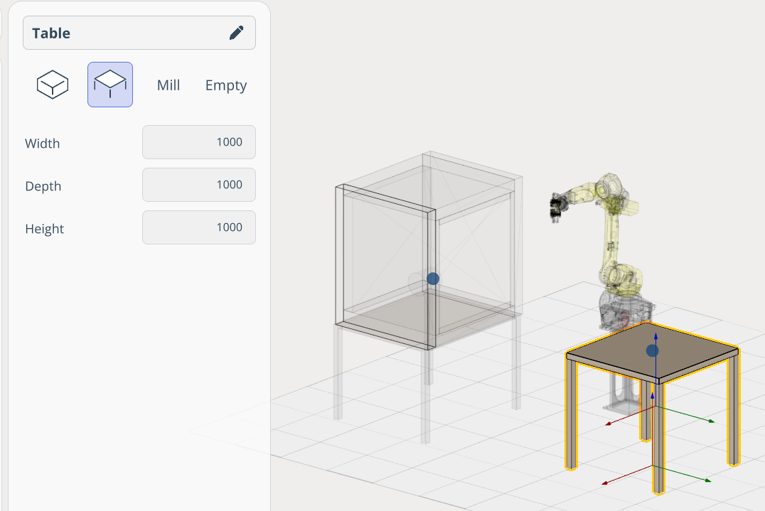
Add a table where the parts will be stored. Add and configure the cell parameters for the table.
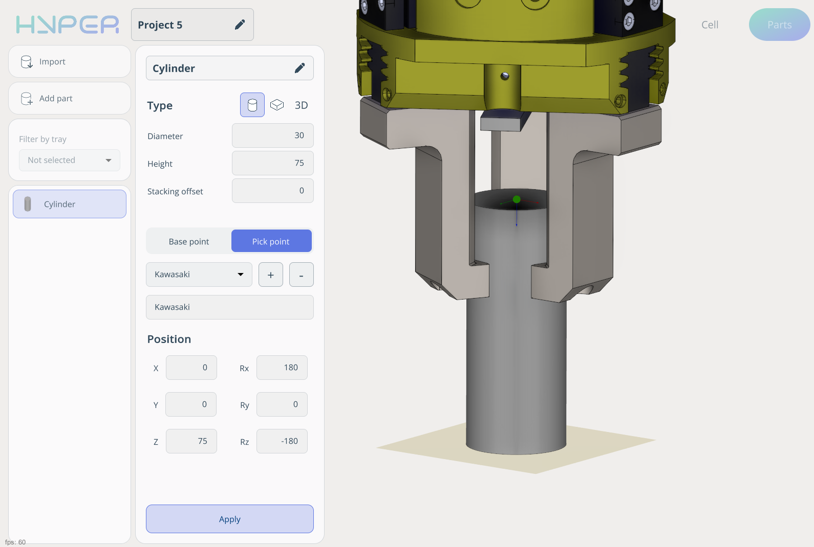
On the Parts tab, create a cylinder and define its Pick Point. Leave the Base Point set to default.
Place the cylinders across the entire cell by holding the left mouse button.
The next step is to build the correct program that enables the robot to transfer parts to the machine for processing.
This robot is equipped with a tool that has two grippers. The logic of our program is to pick up a part and load it into the machine for processing, then place the processed part back onto the table.
To ensure that all parts from the table are used, disable the Single element slider. Also place one part into the machine cell.
As a result, the robot picks up an unprocessed part from the table, then removes the processed part from the machine and replaces it.
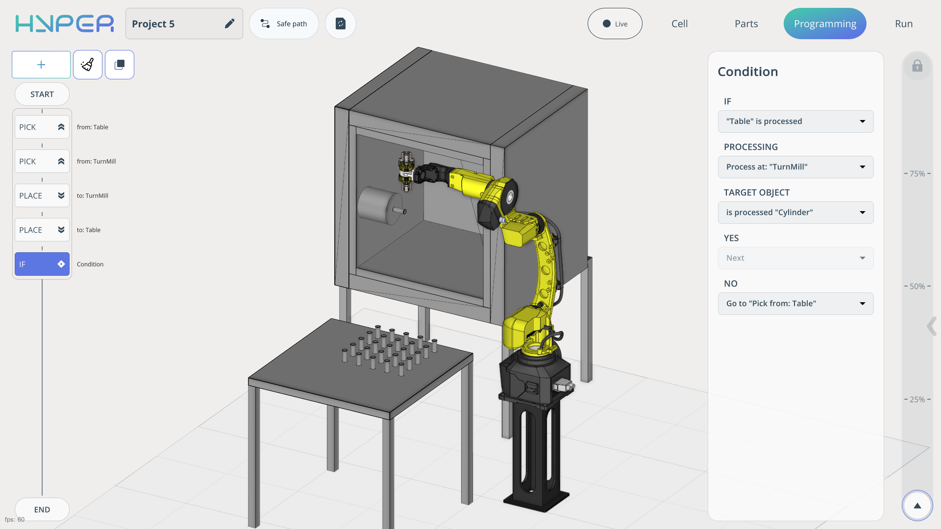
Since we are using multiple parts from the table, the program needs to be looped. To do this, add an IF command and set the parameters required to loop the part transfer and processing workflow.
After recalculating all commands, the trajectory will appear. You can use the speed slider on the right to observe the program execution. The robot should transfer all parts to the machine and return them to the table.