5D Surfacing operation
Application area:
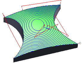
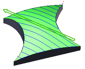
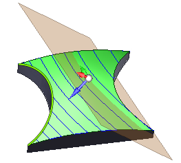
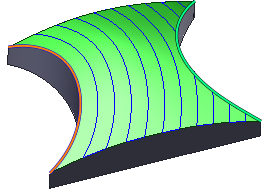
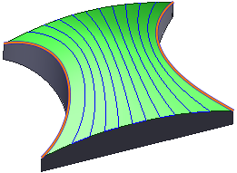
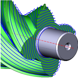
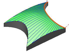
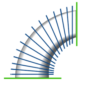
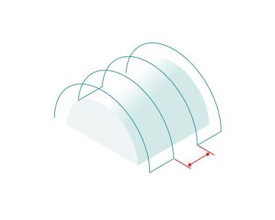
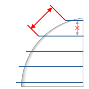
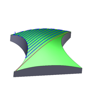
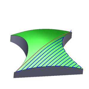
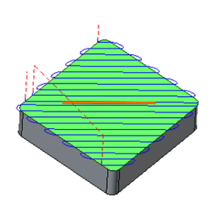
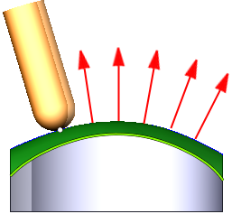
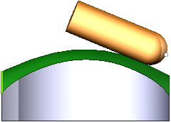
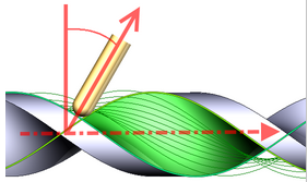
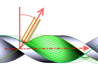
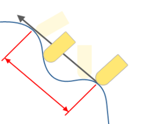
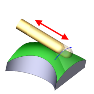
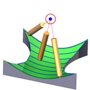
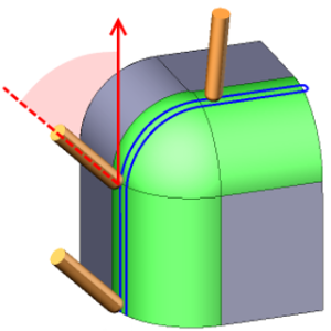
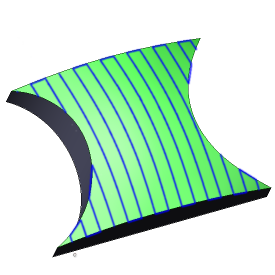
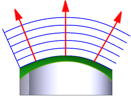
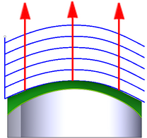
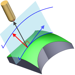
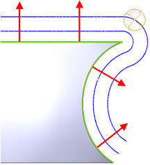
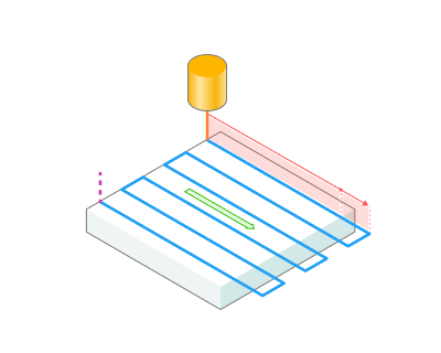
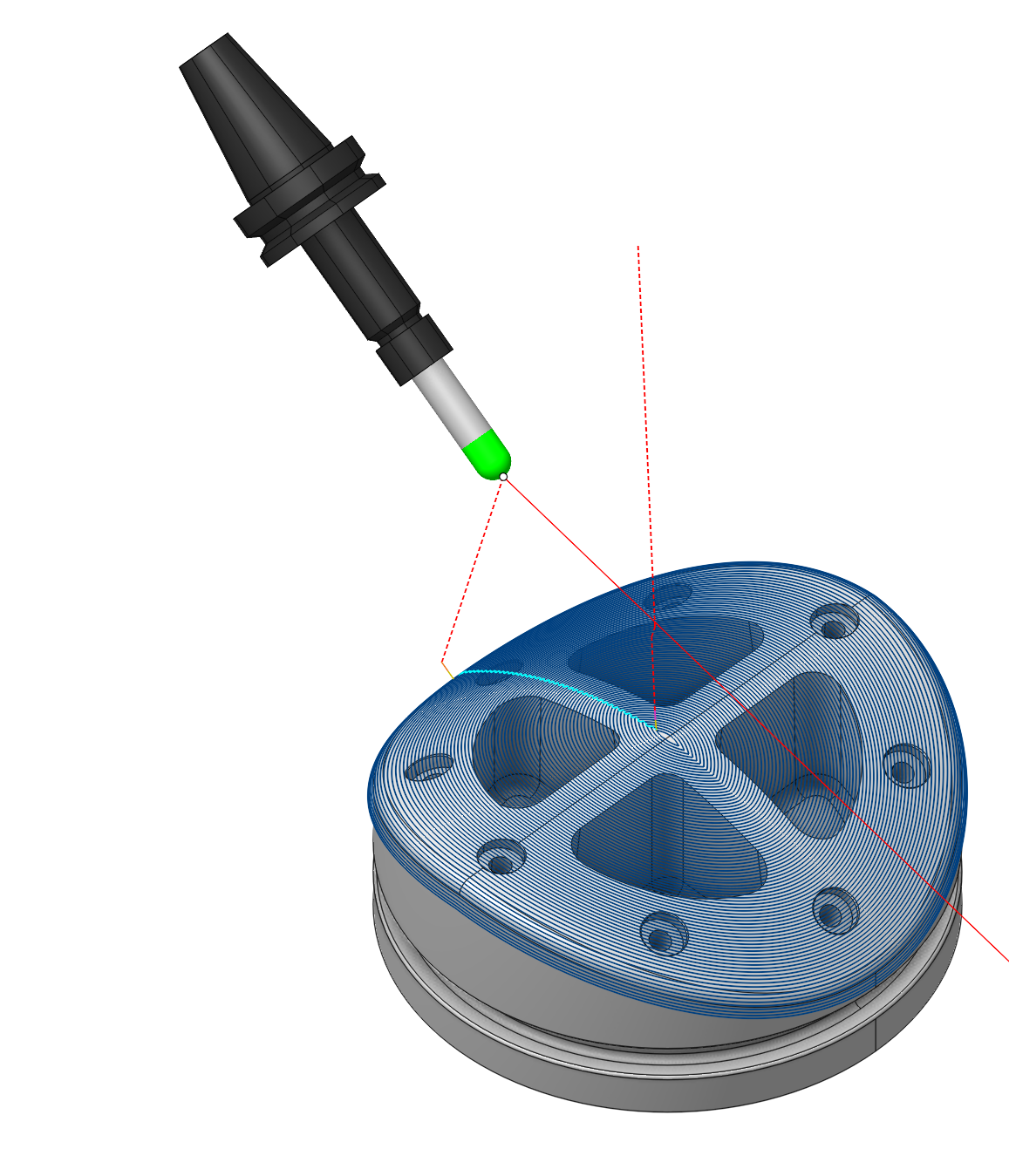
5D Surfacing operation is the operation from the finishing group and enables machining the surfaces of the model with a variety of strategies (parallel to planes, parallel to curve, morph, etc.) and tool axis orientation modes (fixed, normal to surfaces, to rotary axis, through point, through curve, etc.).
Job assigment:
Machining Surfaces. Select various surfaces of the part as the working task. The system will calculate the trajectory based on the chosen surfaces.
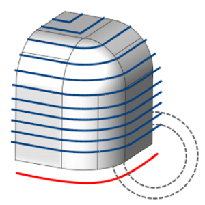
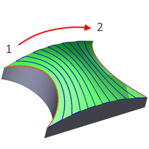
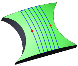
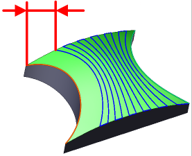
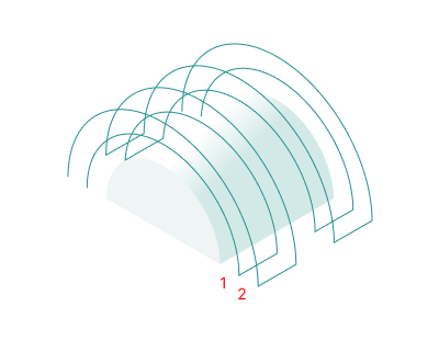
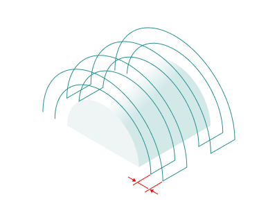
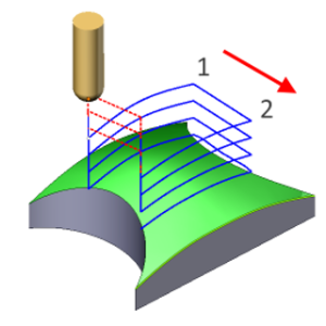
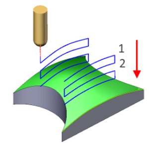
First Curve. For the Parallel to Curve strategy, this feature specifies curves for parallel passes computations. Additionally, in the Morphing Between Two Curves strategy, it specifies the First Curve . You can select one or multiple, not necessarily connected, curves or edges.
Second Curve. The system uses it in he Morphing Between Two Curves strategy. It specifies the Second Curve . You can select one or multiple, not necessarily connected, curves or edges.
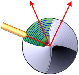
Tilt Curve. This is t he curve that the tool axis vector aims at when setting Tool Orientation specification Through Curve.
Extended Geometry. Specify the surfaces tangentially to which you can extend the toolpath, and the lines across which you can elongate the toolpath.
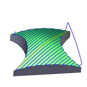
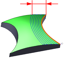
First Surface. This feature s erves as the First Surface in a Morph Between Two Surfaces strategy, facilitating the morphing process to create toolpath lines.
Second Surface.
This feature s
erves as the Second Surface
in a Morph Between Two Surfaces strategy, facilitating the morphing process to create toolpath lines.
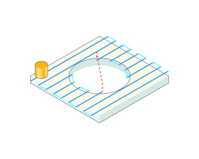
Surfaces for projection. These are the s urfaces intended for machining onto which the toolpath transfers when enabling the Project Toolpath onto the Part option in the Strategy tab.
Job Zone. Use the job zone to trim the passes outside the specified 2d containment areas. The plane of the containment area is defined by the initial tool orientation. See more.
Restrict Zone. In addition to Job Zones in system you can use Restrict Zones geometry from curves and edges to specify the workpiece areas that s hould avoid machining in the current operation. See more
Properties. Displays the properties of an element. It is possible to add the stock. You can also call this menu by double clicking on an item in the list.
Delete. Removes an item from the list.
Strategy:
Strategy:
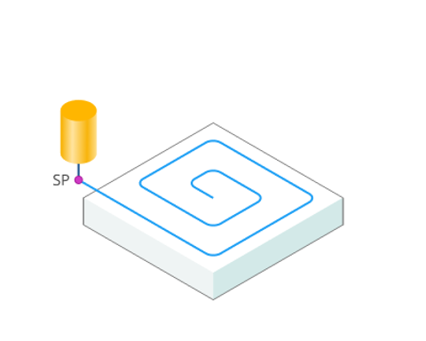
This parameter allows the user to achieve a required toolpath:
Milling Type:
Сan be assigned in almost all operations, except for the curve machining operations. This allows the user to control the required milling type (climb or conventional) during the toolpath calculation process. See more
The parameters of the Milling Type are the same. as in the Waterline Roughing operation. See more.
Sorting:
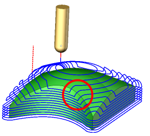
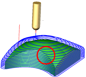
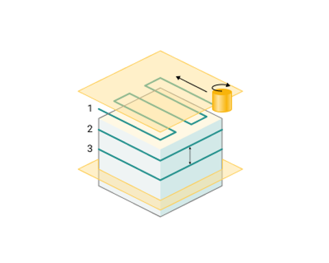
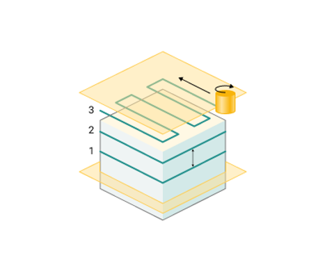
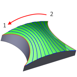
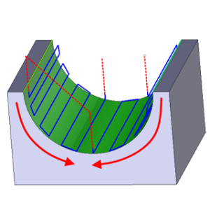
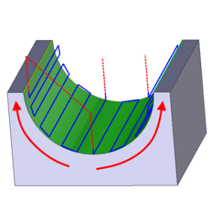
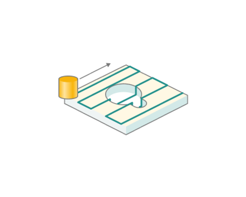
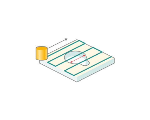
Controls the sequence of toolpath passes during surface machining.
Tool Orientation:
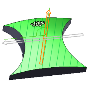
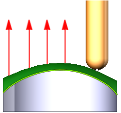
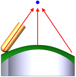
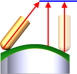
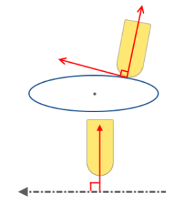
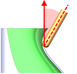
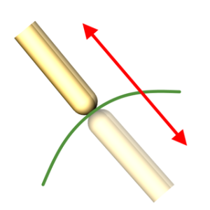
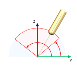
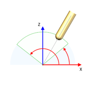
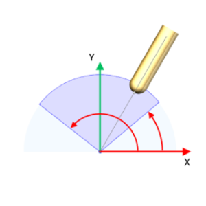
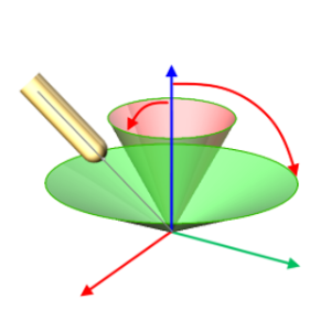
Controls tool axis orientation.
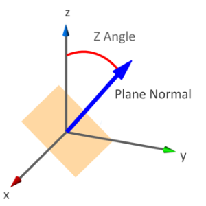
Limit Rotation Angles:
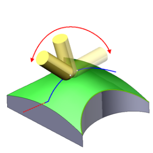
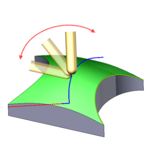
When the flag is set, it specifies the limit values of the tool's angular position relative to the specified axis.
Job zone.
Enables additional modification of the working area initially selected on the Job assignment tab.
Corners smoothing.
When there is a sudden change of the tool direction, the milling control performs deceleration before starting the turn, and then accelerates again. This fact can lead to vibrations and high tool and milling machine wear. The problem can be solved if the toolpath has very few or no breaks. For this reason, in the system there is the toolpath smoothing function using the defined radius for machining inner or outer corners of the model.
Roughing Passes.
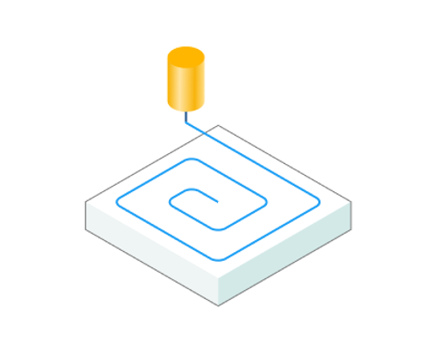
Toolpath is offset in plane by the Roughing passes thickness amount. Additional passes are added to the contour by the value specified in the parameters with the specified number of steps.
Project Toolpath onto the Part:
By setting the flag, the system generates tool paths for processing the surfaces identified as Surfaces for Projection in the Job Assignment by mapping the path derived from the Machining Surface onto the Surfaces for Projection.
Trimming:
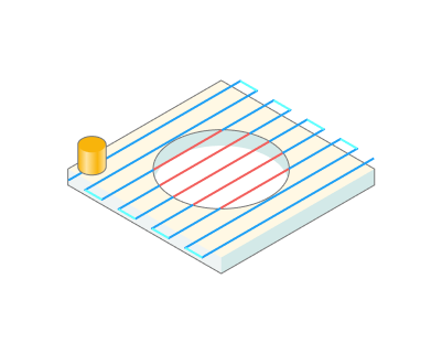
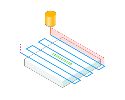
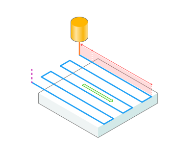
Allows for the skipping of surfaces
not intended for machining
and allows for the extension of the toolpath.
Transformations:
Parameter's kit of operation, which allow to execute converting of coordinates for calculated within operation the trajectory of the tool. See more.
