Tool path errors detected by simulation
Application area:
The section covers error identification in tool paths during simulation, and provides filter controls to selectively display or suppress specific error types for focused analysis.
In the CAM system, on the Technology tab, operations have status indicators reflecting their current state. See more
On the Simulation tab, each CLDATA row has its own status, enabling quick identification of any issues. The status of the node is indicated by an icon:
• ![]() - CLDATA commands are disabled. It is not output to the NC program and not simulated.
- CLDATA commands are disabled. It is not output to the NC program and not simulated.
•![]() - CLDATA commands are not simulated.
- CLDATA commands are not simulated.
•![]() - CLDATA command is simulated without errors.
- CLDATA command is simulated without errors.
• CLDATA command is simulated with error (various icons may appear here; they will be described in detail below.);
•![]()
![]() - CLDATA command is idle. The stock is not removed by this tool motion command.
- CLDATA command is idle. The stock is not removed by this tool motion command.
During operation, various checks are performed. If an error occurs, the CLDATA row is marked with the corresponding icon.
The following types of errors are checked:
• ![]() - Stock removal by rapid feed is forbidden. If the stock is removed and the feed rate is rapid, then the command is marked as an error.
- Stock removal by rapid feed is forbidden. If the stock is removed and the feed rate is rapid, then the command is marked as an error.
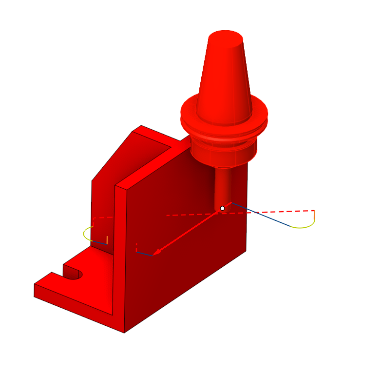
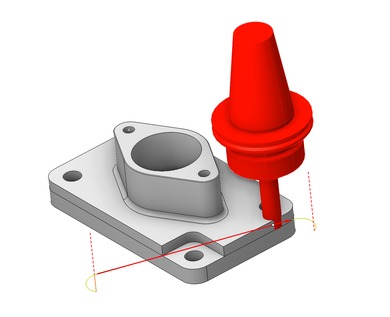
• ![]() - Toolholder collision. If the toolholder touches the workpiece when the CLDATA command is marked as an error;
- Toolholder collision. If the toolholder touches the workpiece when the CLDATA command is marked as an error;
• ![]() - Impossible to calculate the compensation. Tool radius compensation is performed while doing the simulation. The compensation value is defined in the operation parameter window on the tool bookmark. If compensation cannot be made for the CLDATA command, then the motion is marked as an error;
- Impossible to calculate the compensation. Tool radius compensation is performed while doing the simulation. The compensation value is defined in the operation parameter window on the tool bookmark. If compensation cannot be made for the CLDATA command, then the motion is marked as an error;
• ![]() - Tool plunge cuttings with an angle exceeding the maximum value specified in the tool parameters are marked as errors.
- Tool plunge cuttings with an angle exceeding the maximum value specified in the tool parameters are marked as errors.
• ![]() - Collision of machine nodes.
- Collision of machine nodes.
• ![]() - Gouging the part is detected.
- Gouging the part is detected.
• ![]() - Axis travel over the limits.
- Axis travel over the limits.
• ![]() - Inappropriate tool and spindle rotation direction error.
- Inappropriate tool and spindle rotation direction error.
• ![]() - Tool overload (appears if option <
- Tool overload (appears if option <![]() Mark overloads > is enabled in the Adaptive federate section on the Feeds/Speeds parameter panel for roughing waterline operation). See more
Mark overloads > is enabled in the Adaptive federate section on the Feeds/Speeds parameter panel for roughing waterline operation). See more
Collision Check Level Panel.
This panel contains buttons similar to those used for Background Simulation. See more
There are several important considerations when working with this panel:
• By default, on the Simulation tab, the collision check level matches the check level of Background Simulation. That is, when you change the Background Simulation check level in the system settings and click Apply, the collision check level settings on the Simulation tab are automatically updated (Only if the verification level on the Simulation tab was higher than that of Background Simulation).
• On the Simulation tab, you can set a check level that differs from the Background Simulation settings — but not lower than the level defined in Background Simulation. Decreasing the check level is not allowed.
Example. If the Machine check level is selected in Background Simulation, it cannot be lowered below this value on the Simulation tab. However, you can increase the check criterion by moving the slider to the Hidden Nodes position. This will help detect additional errors, if any are present.
• When you increase the check level on the Simulation tab after performing a background calculation, the operation status is reset to the value ![]() . Similarly, changing the Simulation accuracy will also reset the operation status.
. Similarly, changing the Simulation accuracy will also reset the operation status.
• If you run a step‑by‑step simulation and lower the check level below that of Background Simulation, the operation statuses will change depending on the current check level.
Example. If Holder is set as the check level in Background Simulation and a step‑by‑step simulation is then performed with the Hidden Nodes check level, lowering the check level to Machine or Dressing will cause the operation statuses to update. The user will see only those errors that correspond to the selected check level.
Part gouge. Allows displaying errors where gouging of the part has been detected.
Additionally, the system includes dedicated auxiliary buttons that allow users to stop full simulation under different conditions:
•![]() - Allows stopping at CLDATA rows where the M1 stop command is specified. The M1 command can be inserted using the Macro of Toolpath Template functionality. See more For better visualization of the technological process, an Auxiliary operation can be created, and the M1 command can also be set in the Macro of Toolpath Template section. See more
- Allows stopping at CLDATA rows where the M1 stop command is specified. The M1 command can be inserted using the Macro of Toolpath Template functionality. See more For better visualization of the technological process, an Auxiliary operation can be created, and the M1 command can also be set in the Macro of Toolpath Template section. See more
•![]() - Allows stopping after each operation.
- Allows stopping after each operation.
•![]() - The button defines the action, then the error is detected. If the button is down, then the simulation process is break after the error detecting. Else, the node is marked by the red exclamation mark and the simulation process goes on. After the simulation, it is possible to find the marked nodes by shortcuts or from the context menu:
- The button defines the action, then the error is detected. If the button is down, then the simulation process is break after the error detecting. Else, the node is marked by the red exclamation mark and the simulation process goes on. After the simulation, it is possible to find the marked nodes by shortcuts or from the context menu:
![]() - Go To Next error – move the selection to the next error, marked node;
- Go To Next error – move the selection to the next error, marked node;
![]() - Go To Previous error – move the selection to the previous error marked node.
- Go To Previous error – move the selection to the previous error marked node.