Turning grooving cycle
INCT_LatheGroovingCycleFormer - a CAM system interface that simplifies forming the movements of a turning grooving cycle. The object implementing this interface is returned by the function INCT_CLData.CreateLatheCycleFormer, INCT_GeomCLData.CreateLatheCycleFormer when it is called with the lctGrooving parameter.
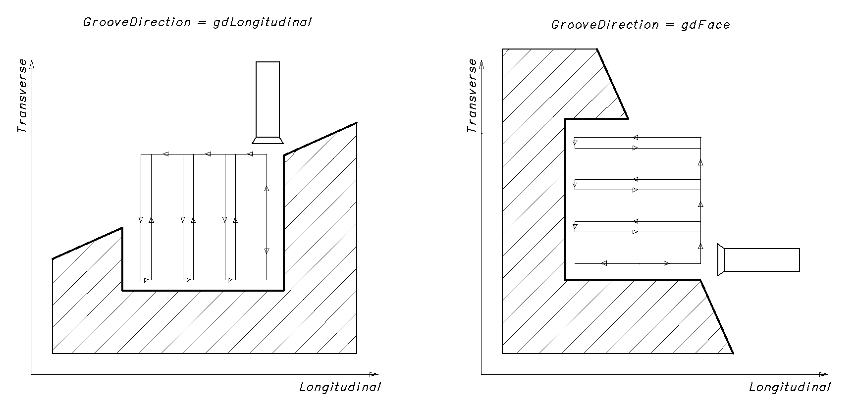
Purpose:
The movements in the various types of grooving cycles generally follow the same tool path on different controllers:
- Moving to the start point or to the next plunge point at rapid traverse.
- Plunging to the groove depth in one pass or in several steps by the depth of cut at working feed, with retraction for chip breaking.
- Returning to the start position with or without retraction at transition feed.
- If the groove width is not reached, returning to step 1.
Example of such a cycle: Sinumerik: CYCLE93.
The generator forms the tool path from the specified parameters: groove start and end points, step across the groove width, depth of cut, retraction distance, etc. It also allows adding to any section of the tool path the features required by a particular cycle, changing the feed type or value, or skipping a tool movement prepared by the generator.
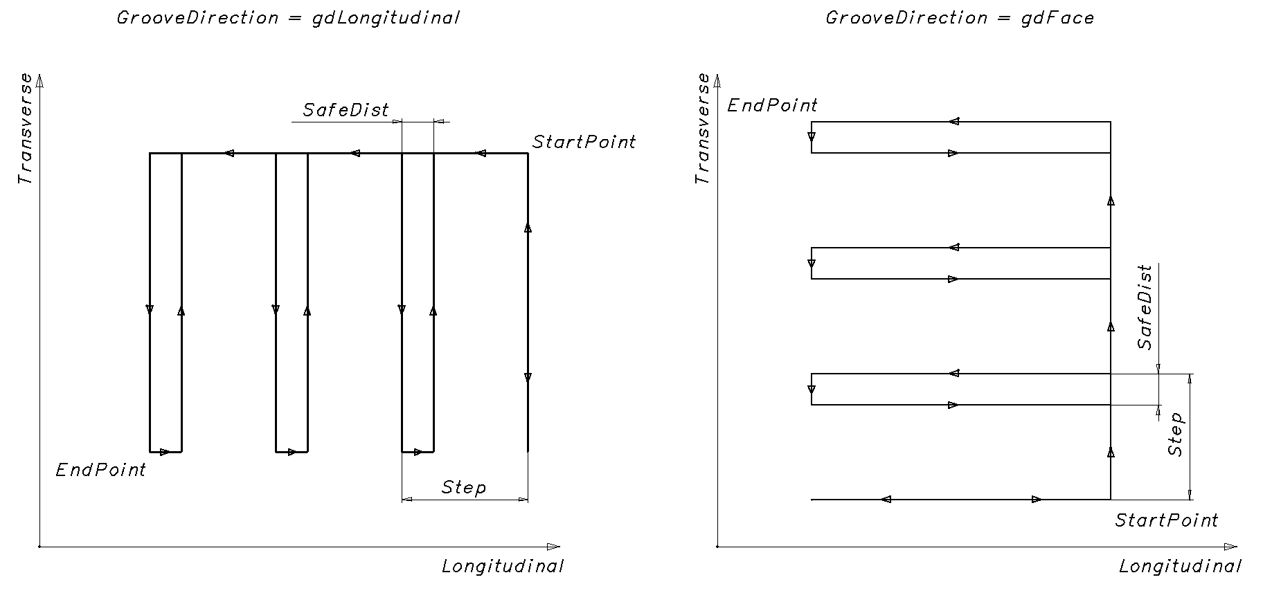
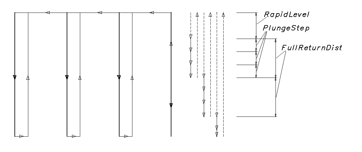
Using the generator:
We recommend creating a new turning cycle generator for each new cycle in a block of the NC program, except when the cycle is repeated in a new block. Therefore, the interface of the old generator must be released when a new one is created or when the interpreter finishes its work.
To form the tool movement commands along the cycle path, do the following:
- Get the generator interface (INCT_CLData.CreateLatheCycleFormer, INCT_GeomCLData.CreateLatheCycleFormer).
- Set the indexes of the longitudinal and transverse axes along which the movements are made (Set_AxisIndexes).
- Set the groove start point (Set_StartPoint).
- Set the groove end point (Set_EndPoint).
- Set the groove direction (Set_GrooveDirection).
- Set the step across the groove width (Set_Step).
- Set the retraction distance for the return (Set_SafeDist).
- Set the depth of cut in the axial direction (Set_PlungeStep).
- Set the retraction distance for chip breaking (Set_ReturnDistance).
- Assign a cycle event handler (Set_Events) if the cycle path needs to be changed.
- Form the tool movement commands along the cycle path (MakeWorkpath).
Description of the interface methods:
| Method | Method description |
|---|---|
| Set_AxisIndexes | The method sets the indexes of the longitudinal and transverse axes along which the movements are made when the cycle path is formed. Input parameters: Value (TNCLCAxisIndexes) - Transverse (integer) - index of the transverse axis, Longitudinal (integer) - index of the longitudinal axis. No output parameters. |
| Get_AxisIndexes | The function returns the indexes of the longitudinal and transverse axes along which the movements are made when the cycle path is formed (TNCLCAxisIndexes). No input parameters. |
| Set_StartPoint | The method sets the coordinates of the groove start point. Input parameter: Value (TNC2DPoint) - coordinates of the start point (Transverse - transverse, Longitudinal - longitudinal). No output parameters. |
| Get_StartPoint | The function returns the coordinates of the groove start point (TNC2DPoint). No input parameters. |
| Set_EndPoint | The method sets the coordinates of the groove end point. Input parameter: Value (TNC2DPoint) - coordinates of the end point. No output parameters. |
| Get_EndPoint | The function returns the coordinates of the groove end point (TNC2DPoint). No input parameters. |
| Set_GrooveDirection | The method sets the groove direction. Input parameter: Value (TNCGrooveDirection) - groove direction. gdLongitudinal - longitudinal groove; gdFace - face groove. No output parameters. |
| Get_GrooveDirection | The function returns the groove direction (TNCGrooveDirection). No input parameters. |
| Set_Step | The method sets the step across the groove width in the radial direction. Input parameter: Value (real number) - step. No output parameters. |
| Get_Step | The function returns the step across the groove width in the radial direction (real number). No input parameters. |
| Set_SafeDist | The method sets the side retraction distance before the tool exits. Input parameter: Value (real number) - side retraction distance. No output parameters. |
| Get_SafeDist | The function returns the side retraction distance before the tool exits (real number). No input parameters. |
| Set_PlungeStep | The method sets the step of plunging to the groove depth. Input parameter: Value (real number) - step. No output parameters. |
| Get_PlungeStep | The function returns the step of plunging to the groove depth (real number). No input parameters. |
| Set_ReturnDistance | The method sets the upward retraction distance for chip breaking. Input parameter: Value (real number) - upward retraction distance. No output parameters. |
| Get_ReturnDistance | The function returns the upward retraction distance for chip breaking (real number). No input parameters. |
| Set_ReturnDistanceInsidePlungeStep | The method sets the flag “Retraction inside the plunge step”. True - the retraction is included in the plunge step, False - the retraction is added to the plunge step. Input parameter: Value (boolean) - flag value. No output parameters. 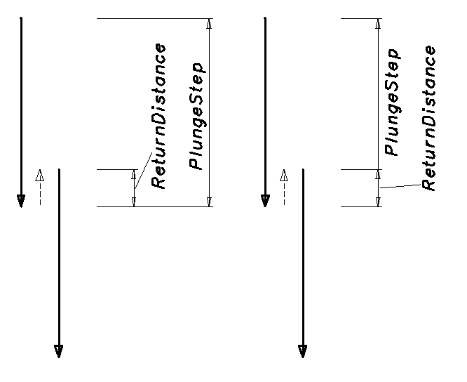 |
| Get_ReturnDistanceInsidePlungeStep | The function returns the flag “Retraction inside the plunge step”. No input parameters. |
| Set_RapidLevel | The method sets the rapid level. Input parameter: Value (real number) - rapid level. No output parameters. |
| Get_RapidLevel | The function returns the rapid level. No input parameters. |
| Set_FullReturnDist | The method sets the retraction distance to the rapid level. Input parameter: Value (real number) - retraction distance to the rapid level. No output parameters. |
| Get_FullReturnDist | The function returns the retraction distance to the rapid level. No input parameters. |
| Set_Feedrate | The method sets the working feed. Input parameter: Value (real number) - working feed. No output parameters. |
| Get_Feedrate | The function returns the working feed. No input parameters. |
| Set_MPM | The method sets the working feed units. Input parameter: Value (boolean) - working feed units. True - mm/min, False - mm/rev. No output parameters. |
| Get_MPM | The function returns the working feed units. No input parameters. |
| Set_Events | The method assigns events that control the cycle behavior. Events allow adding to any section of the tool path the features required by a particular cycle, changing the feed type or value, or skipping a tool movement prepared by the generator. Input parameter: Value (INCT_LatheCycleEvents) - object implementing the events. See the detailed description below. No output parameters. |
| Get_Events | The function returns the object implementing the events that is linked to the generator (INCT_LatheCycleEvents). No input parameters. |
| MakeWorkpath | The method forms the cycle path from the specified parameters. |
INCT_LatheCycleEvents - an interface implemented in the interpreter that allows controlling the behavior of a turning cycle. The interface is a set of event methods executed during the tool movements inside the generator. With these methods, the features required by a particular cycle (dwell, oriented spindle stop, etc.) can be added to any section of the tool path, the feed type can be changed, or a tool movement prepared by the generator can be skipped.
If events are assigned to the generator, every tool movement inside the generator consists of 3 stages:
- The INCT_LatheCycleEvents.BeforeMove method is executed. It receives the values set by the cycle: movement type, coordinates of the movement point, feed type.
- The INCT_LatheCycleEvents.OnMove method is executed. It receives: movement type, coordinates of the movement point, feed type and the flag of whether the movement has been made. All parameters except the movement type can be changed in the implementation. Depending on the flag set in OnMove, the tool moves to the specified point with the specified feed, or the movement is not made.
- The INCT_LatheCycleEvents.AfterMove method is executed. It receives the values returned by OnMove: movement type, coordinates of the movement point, feed type.
Description of the interface methods:
| Method | Method description | Description of use |
|---|---|---|
| BeforeMove | The method is executed before each tool movement when the cycle path is formed. Input parameters: MoveType (TNCLatheCycleMoveType) - movement type, see the description below; Point (TNC2DPoint) - coordinates of the movement point (Transverse - transverse, Longitudinal - longitudinal); Feed (TNCFeedType) - feed type. lmMoveToStartPoint - movement to the groove start point; lmMoveToNextGroove - movement to the next groove step; lmMoveToNextLevel - movement to the next plunge depth; lmMoveToBottomLevel - movement to the groove bottom; lmChipBreaking - chip breaking; lmRetractSideways - side retraction before the tool exits; lmReturnToTopLevel - return to the initial level; lmReturnToStartPoint - return to the start point; lmCutTheThread - thread cutting (for the Turning threading cycle); lmApproach - approach (for the Turning stock removal cycle); lmRetract - retract (for the turning stock removal cycle); lmWorkingMove - working movement (for the turning stock removal cycle); lmOverlapContour - pass along the contour (for the turning stock removal cycle); lmReturnToSafeDistance - return to the safe distance (for the turning stock removal cycle); lmTtransition - transition (for the turning stock removal cycle); lmMoveToRapidLevel - return to the rapid level (tool exit). No output parameters. |
If some commands must be added before a movement, add them to the method implementation. For example, to turn on the machine coolant before grooving, call INCT_CLData.AddCoolant with the appropriate parameters in the BeforeMove implementation under the condition MoveType = lmMoveToStartPoint. |
| OnMove | The method is executed immediately before each tool movement when the cycle path is formed. Input parameters: MoveType (TNCLatheCycleMoveType) - movement type, see the description above; Input and output parameters: Point (TNC2DPoint) - coordinates of the movement point; Feed (TNCFeedType) - feed type; Handled (boolean) - flag of whether the movement has been made inside the implementation (True - the movement has been made, False - it has not). If Handled is True after the OnMove call, the movement has been made inside the OnMove implementation, and the generator does not add a movement command to the tool path. If Handled is False after the OnMove call, the generator considers that the movement has not been made and adds to the tool path a command to move to the point Point with the feed type Feed. |
To override the movement point or the feed, or to skip the movement. For example, to switch to rapid traverse when returning to the initial level after grooving, in the OnMove implementation set the returned Feed parameter to ffRapid under the condition MoveType = lmReturnToTopLevel (for the feed type, see OutStandardFeed). To move the tool to a point other than the one calculated by the cycle, change the Point parameter returned by OnMove. If the movement to the calculated point is not needed, set the Handled parameter to True inside the OnMove implementation. |
| AfterMove | The method is executed after each tool movement when the cycle path is formed, even if the movement has been canceled in OnMove. Input parameters: MoveType (TNCLatheCycleMoveType) - movement type, see the description above; Point (TNC2DPoint) - coordinates of the movement point; Feed (TNCFeedType) - feed type. No output parameters. |
If some commands must be added after a movement, add them to the method implementation. For example, to add a dwell at the groove bottom, call INCT_CLData.AddDelay with the appropriate parameters in the AfterMove implementation under the condition MoveType = lmMoveToBottomLevel. |