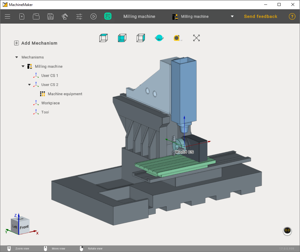
Machine equipment configuration
At the very beginning, before adding the machine equipment, we should prepare our machine and add the attachment points for our machine equipment.
To add connection points, click the plus button in the kinematics tab when editing your machine and select the desired connection.
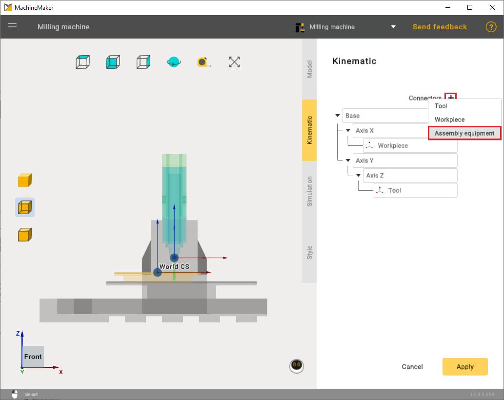
After that, in the kinematics tree, you need to attach the points to the desired axis and position them on the machine.
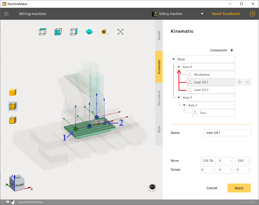
You can download examples of machine and machine equipment here:
Machine equipment has 2 types of axles:
1) Rotary type;
2) Linear type.
In this chapter we will briefly look at the settings of these two types
To add machine equipment use the "Add Mechanism" button.
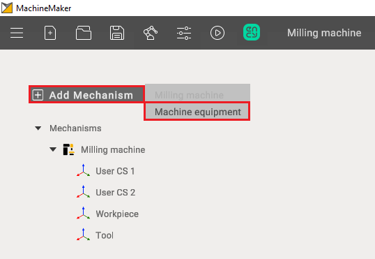
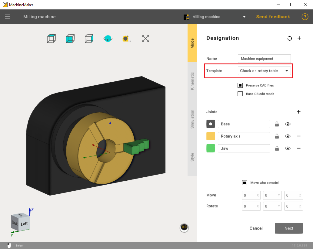
After importing machine equipment, select the appropriate template. Also mark the machine equipment elements with the correct color.
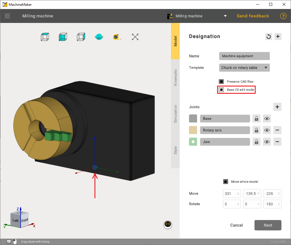
Additionally, if necessary, correctly set the point through the Base CS edit mode to ensure that the machine equipment is properly secured on the machine in the future.
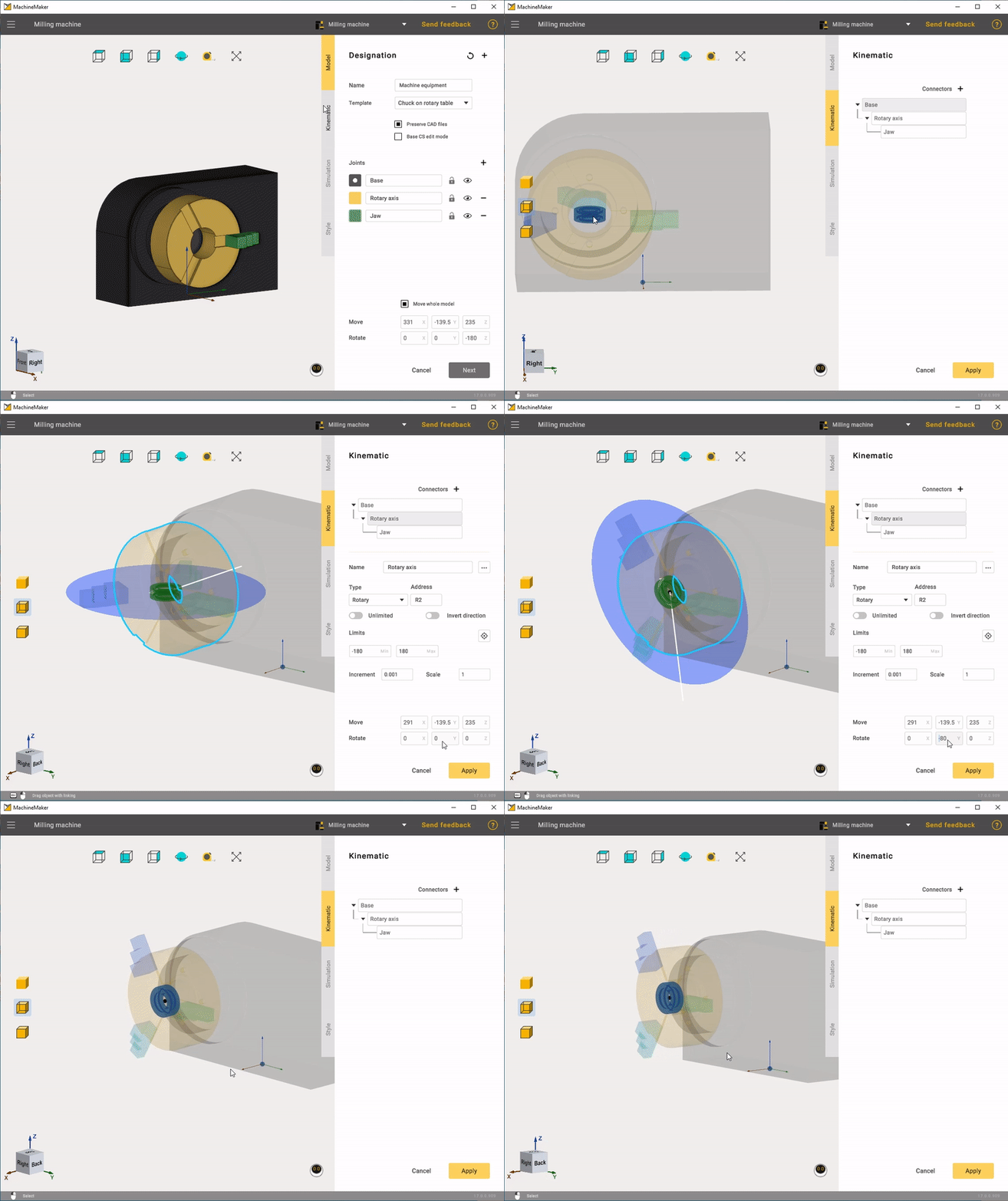
In the Kinematic settings, it is important to correctly set the rotary axis.
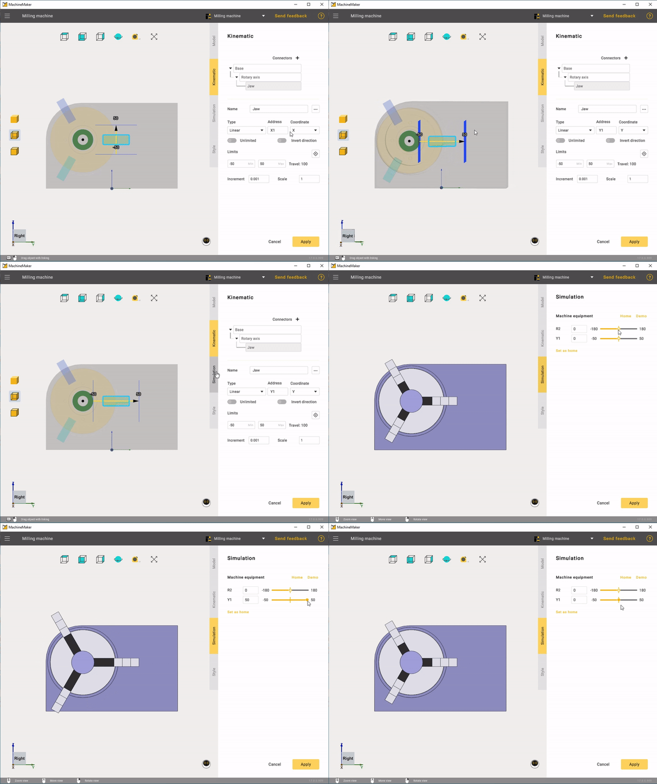
It's also crucial to provide the correct coordinates for the jaws.
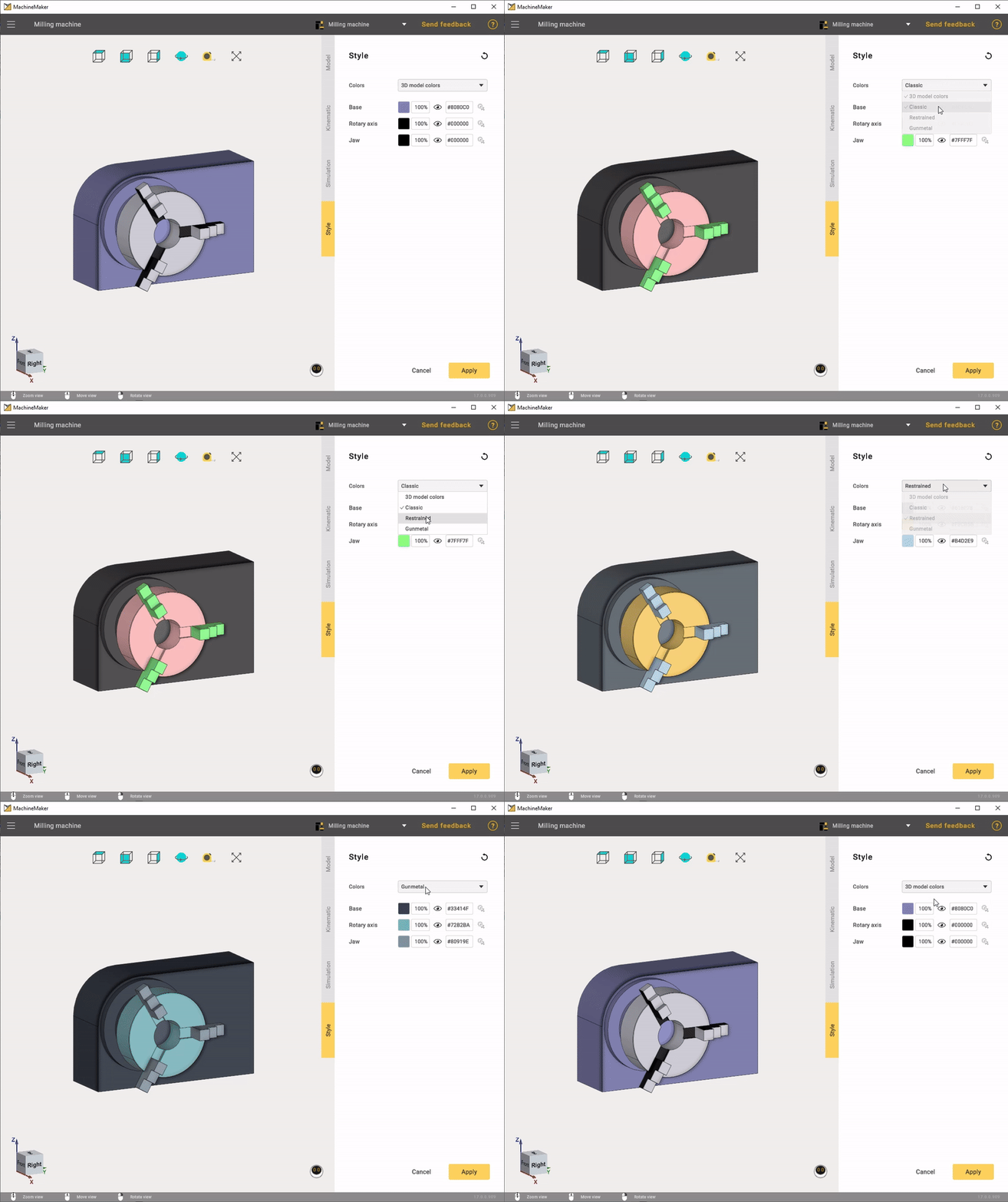
In the Style mode, you can adjust colors to match the machine or choose a custom color.
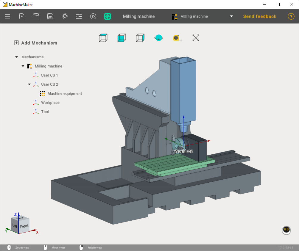
After all settings have been applied, you will need to position the machine equipment on the previously set point.
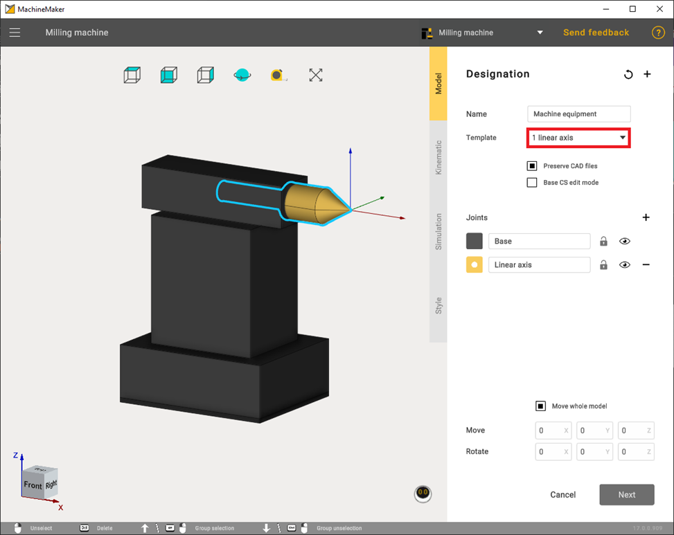
In the second case, let's consider an example of machine equipment with a linear axis. The settings are straightforward. You need to select the appropriate template and configure the motion coordinates of the linear axis.
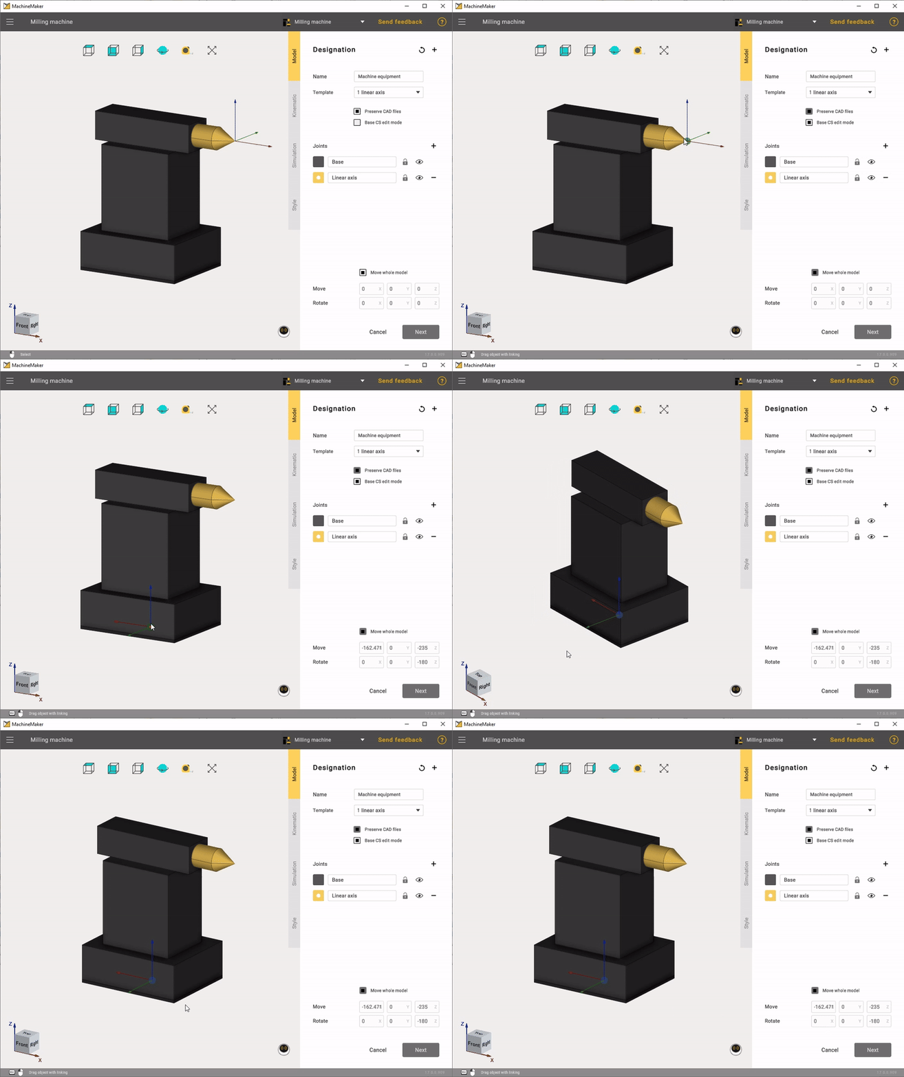
Also, if necessary, it is advisable to correctly set the point through the Base CS edit mode so that the machine equipment is securely attached to the machine in the future.
The setting of the linear type is the same as that of the rotary type. You must also set the jaw movement limits.
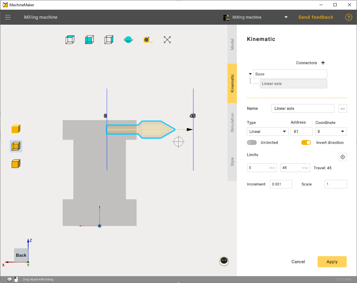
In simulation mode, check that everything is working correctly.
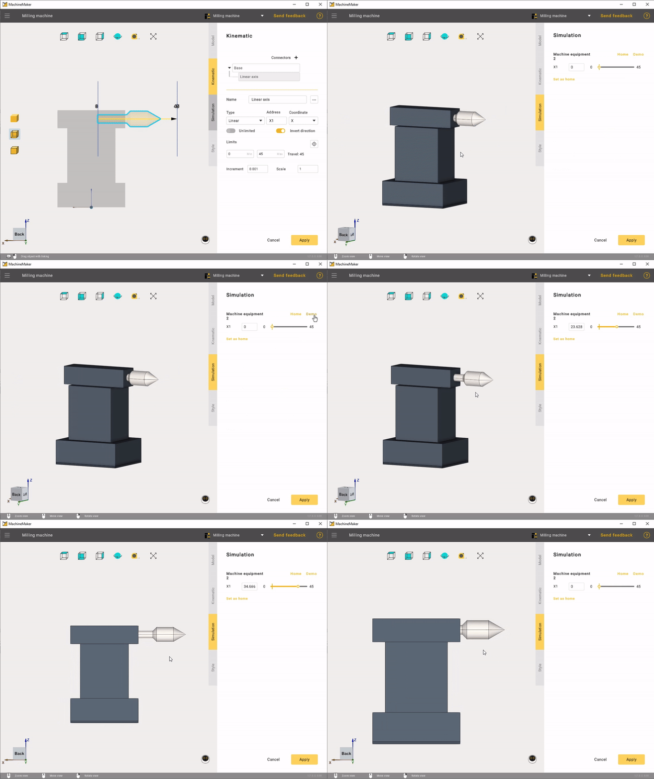
In the end it was possible to assemble a machine with two machine equipment.
