Drilling cycle with shift
INCT_DrillingCycleWithShiftFormer — CAM system interface that implements the functionality to simplify the formation of movements in the drilling cycles with a shift. When called with the dctWithShift parameter, the INCT_CLData.CreateDrillingCycleFormer, INCT_GeomCLData.CreateDrillingCycleFormer function returns as a result an object that implements two interfaces: INCT_DrillingCycleFormer, INCT_DrillingCycleWithShiftFormer.
Through the INCT_DrillingCycleFormer interface, basic parameters are set for the shift drilling cycle. A description of the use is given in this article of the Drilling cycle.
INCT_DrillingCycleWithShiftFormer interface adds to the shaper implementation the ability to control the path construction parameters with a shift.

Purpose:
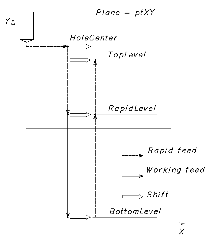
Displacements in different drilling cycles with a shift, for different controllers, generally repeat the same trajectory:
Positioning the tool over the center of the hole/next hole in the accelerated feed.
Move the tool to the level of the accelerated movement at the accelerated feed.
Move the tool to the bottom of the hole in the work feed.
Returns to the level of accelerated movement at an accelerated feed.
Return to retract/return level in expedited feed.
If the number of repetitions is not over, return to step 1.
In one or several sections of such cycles, the tool movement path is displaced along one or several axes. Examples of such cycles are Fanuc: G76, G87; Sinumerik: CYCLE86; Heidenhain: CYCL DEF 202, etc.
Former use:
We recommend creating a new drilling cycle former for each new cycle in the NC-code frame, except for cases of repeating the cycle operation in a new frame (analogue of the CYCL CALL for Heidenhain). Thus, the interface of the old former must be freed when creating a new one or shutting down the interpreter.
Using the INCT_DrillingCycleFormer interface allows you to set the tool path according to the specified parameters: initial position, levels of accelerated movement, bottom of the hole, number of repetitions, etc. And also add to the tool path any formed section features necessary for a specific cycle: dwell, oriented stop, threading, etc., change the type or value of the feed, or skip the tool path prepared by the former.
Using the INCT_DrillingCycleWithShiftFormer interface allows you to set the shift to the coordinates of the tool movement points at any of the stages of the cycle, except the first one. At each of the specified stages, the tool is moved from the current point to a new point as follows:
moving from the current point to the current shift point;
moving from the current shift point to a new shift point;
move from a new shift point to a new point.
To form commands for moving a tool along a cycle path, the following steps must be performed:
Get the former interfaces (INCT_CLData.CreateDrillingCycleFormer, INCT_GeomCLData.CreateDrillingCycleFormer with the parameter dctWithShift).
Set the indexes of the axes X, Y, Z on which the movements will be made (Set_AxisIndexes).
Set the current plane (Set_Plane).
Set the hole center point value (Set_HoleCenter).
Set the hole center point mode (Set_HoleCenterMode).
Set the level of accelerated movement (Set_RapidLevel).
Set the bottom hole level (Set_BottomLevel).
Set the top level (Set_TopLevel).
Set the feedrate (Set_Feedrate), feedrate units (Set_MPM).
Set the number of repetitions of the cycle (Set_Count).
If the loop trajectory needs to be modified, set the loop event handler (Set_Events).
Set the shift type of tool moving points (SetShiftByOneAxis or SetShiftBySomeAxis).
Set the areas of the tool path on which the shift will be used (Set_ShiftPathSet).
Form teams of tool path along the cycle path (MakeWorkpath).
Description of INCT_DrillingCycleWithShiftFormer interface methods:
|
Method |
Method Description |
|
SetShiftByOneAxis |
The method switches the type of shift calculation to the value “Single axis calculation” and the shift size. In this case, for all stages, the shift will be made along one of the axes depending on the plane specified in Set_Plane: for ptXY along the X axis, for ptYZ along the Y axis, for ptZX along the Z axis. Input parameter: Value (number) — the shift value. No output parameters. |
|
SetShiftBySomeAxis |
The method switches the calculation type of shift to the value “Calculation by selected axes” and sets the size of shift for each axis. In this case, the shift of the level point of the hole bottom will be made along the selected axes with the specified values. For the remaining levels, the shift will be made along the selected axes, except the drilling axis, also with the specified values, along the drilling axis without shift. Input parameter: Axis (TNCShiftAxis.X, Y, Z — logical) axes along which offsets are performed; Values (TNCShiftValues.X, Y, Z — number) — the values of the offsets along the axes. No output parameters. |
|
Set_ShiftPathSet |
The method sets the stages in the tool path at which the cycle former will do the shift. Input parameter: Value (TNCShiftPathSet) — a set of path stages at which the loop former will make a shift. You can select several stages of the path. spMoveToRapidLevel — when moving to the rapid level; No output parameters. |
|
Get_ShiftPathSet |
The function returns the specified stages in the tool path on which the cycle former will make the shift (TNCShiftPathSet). |
|
Get_ShiftNextHole |
The function returns the coordinates of the point of the current hole with shift, calculated for the current iteration (TNC3DPoint). Value is available for use only inside the events. (Set_Events). |
|
Get_ShiftRapidPoint |
The function returns the coordinates of the accelerated displacement point calculated for the current iteration with the shift (TNC3DPoint). Value is available for use only inside the events (Set_Events). |
|
Get_ShiftTopPoint |
The function returns the coordinates of the point of retract/return calculated for the current iteration with shift (TNC3DPoint). Value is available for use only inside the events. (Set_Events). |
|
Get_ShiftBottomPoint |
The function returns the bottom point coordinates calculated for the current iteration with shift (TNC3DPoint). Value is available for use only inside the events (Set_Events). |