Geometrical model structure window
The model structure window consists of three panels: the <tools panel>, the <model tree> and a <list of available objects>.
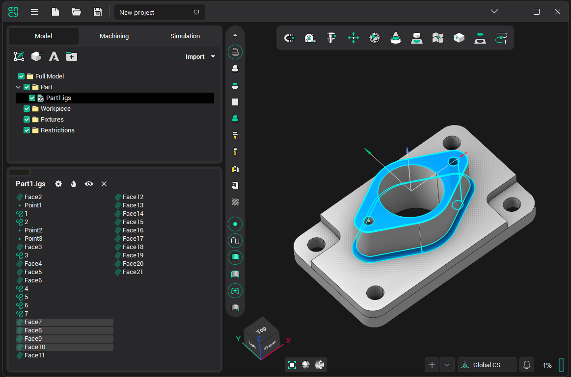
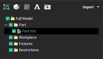
In the <model tree> panel above, the structure of the whole model is displayed. Three nodes make up the groups of the model, which are located at different levels. The active groups are highlighted. When selecting an inactive group using the mouse or keyboard, the group becomes active and the list of available objects changes accordingly.
Below, commands from pop-up windows will be considered, repeated commands will be skipped.
Clicking the right mouse button on a normal group in <model tree> brings up the following pop-up window:
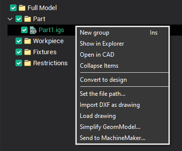
Commands:
New group - adds a new object the active group.
Import DXF as sketch, Load sketch - commands for work with sketches.
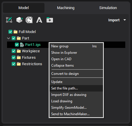
Clicking the right mouse button on the node of the imported model in the <model tree> causes the following pop-up window:
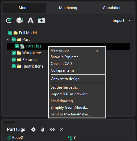
Commands:
Show in Explorer - will open the folder, where contains the imported file;
Open in CAD - file will be opened in the linked CAD, if not, then window selection appears.
If the imported file has been changed, the name of the group will be allocated "bold", the toolbar button appears "Model files update manager"  , and the Update (update only selected group) command will appear in a pop-up window:
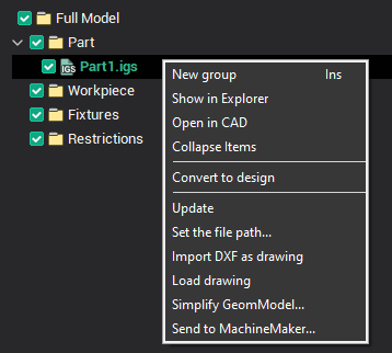
If the imported file has been renamed, moved or deleted, the Set File Path... (allows you to specify the new location of the imported file) command will appear in a pop-up window.
Clicking the right mouse button on any group in the <list of available objects> causes the following pop-up window:
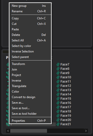
Commands:
Rename - allows you to edit the name of the selected object;
Copy, Cut, Paste - working with the exchange buffer;
Delete - deletes selected objects;
Select All - selects all geometric objects;
Select by color - selects all objects in the tree that have the same color as the selected one:
Inverse Selection - selects all other objects, and the selection of current cancels;
Transform, Join, Project, Triangulate - commands are duplicated on <tool panel> and described below;
Inverse - inverting normals of surfaces;
Color - allows you to change the color of the selected object;
Save as... - offers to save the selected geometric objects in one of the supported formats;
Save as tool... - saves the selected object in the form of an arbitrary shaped tool;
Save as tool holder - saves the selected object in the form of an arbitrary holder;
Properties - calls the properties window of geometric objects.
In the <list of available objects>, all groups and geometrical objects, which are a part of the active group, are displayed. That is, the objects which are currently available for selection and modification. Single left mouse clicking on any of the listed objects, selects that object.
![]()
 – Viewing and editing properties of selected objects.
 – Setting color of selected objects.
 – Set selected surfaces visible/invisible.
 – Deletes selected objects.
 – Starts the CAM system CAD drawing.

 – Spatial transformations of selected objects.
 – Getting curves as section of 3D model by plane.
 – Surfaces boundary projection on plane.
 – Sew faces.
 – Triangulation of selected curves or patching holes in meshes.
See also: