Main window
Application area:
The content of the main window’s elements depends on the 2D or 3D working mode.
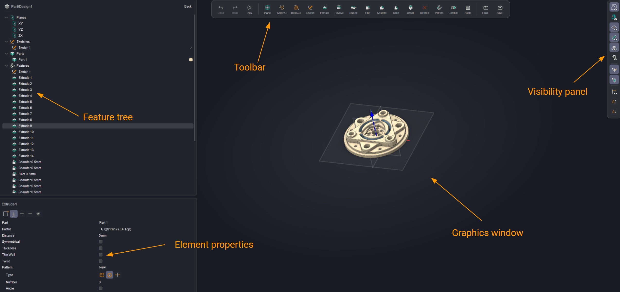
The main window consists of a feature tree, a toolbar, element properties, and a visibility panel.
Feature tree.
The feature tree displays the chronological sequence of operations performed to create the 3D model. It is important to note that the feature tree is strictly sequential. Therefore, it is not possible to create two non-intersecting extrusions within a single body. The system will require the creation of a new body.
The tree consists of 3 base planes, sketches, parts and features.
Sketches. Defines a drawing in the construction tree
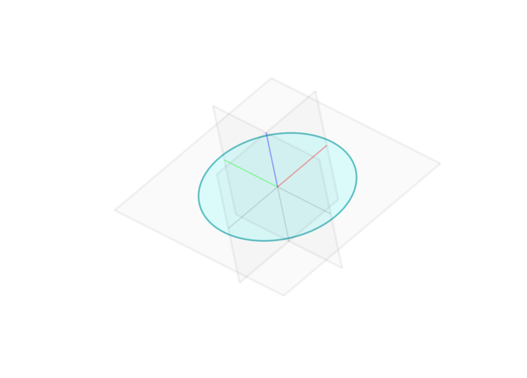
Planes are created using a pop-up menu (by clicking the right or left mouse button on a surface or plane). Its content changes depending on the selected element.

Then you need to click on the drawing button.
![]()
The methods for defining a plane are described in another chapter. See more
Next to each sketch in the tree, there is a visibility toggle that allows you to show or hide it in 3D mode.

If the contour is closed, the system highlights it, indicating that a boolean operation can be performed.
If the contour is not highlighted for extrusion, check the sketch visibility and ensure that the contour is closed.
Curves. They represent spatial curves (Helix, Spline). See more
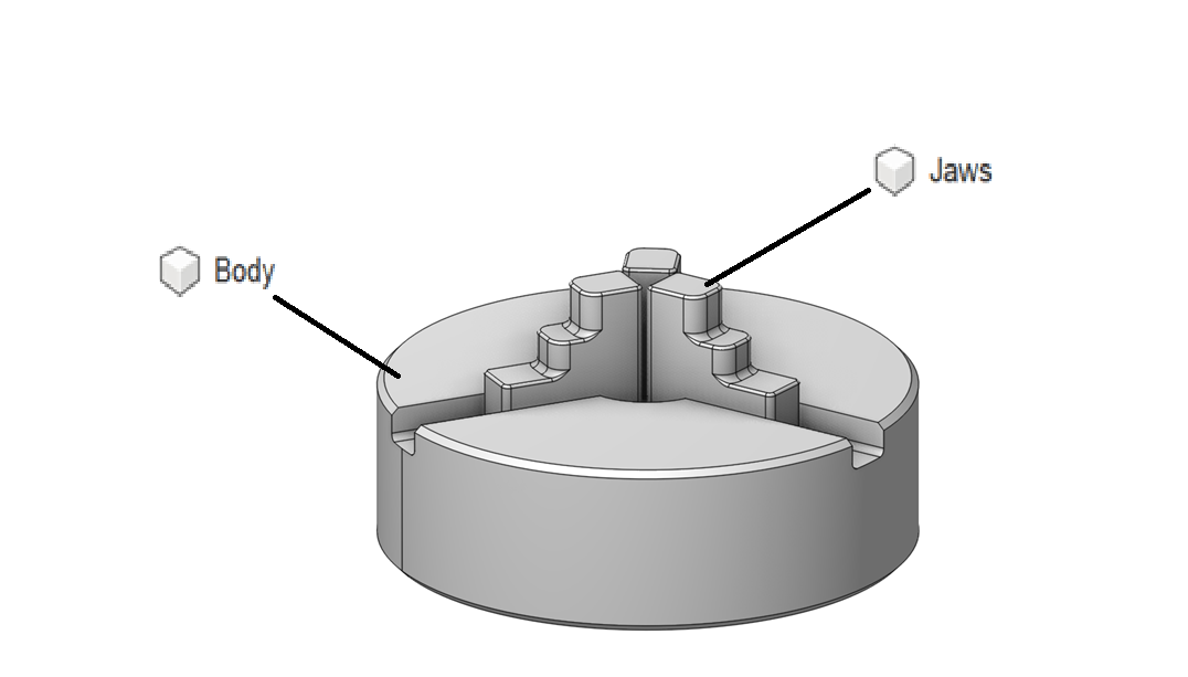
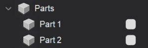
Parts. The Design can consist of multiple parts (one by default). This allows for the creation of assemblies from individual parts. This is necessary for creating assemblies (for example, a jaw chuck consists of jaws and a base). See more
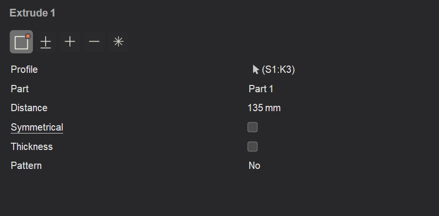
The Create Part button is located in the Element Properties panel when performing the Extrude command.
To have two parts appear in the tree, you need to create at least two sketches and perform the Extrude operation on each.
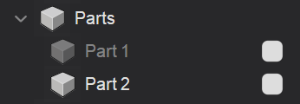
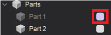
The visibility of a part is controlled by clicking its icon.
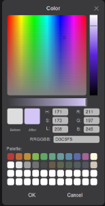
You can also change the color of the model.
Features. It contains various elements (sketches, extrudes, etc.).
Toolbar.
This is the toolbar for 2D (See more) or 3D (See more) mode. The toolbar’s contents change depending on the selected mode.
Element properties.
This panel allows you to change the properties of Features.
Visibility panel.
This panel allows you to control the visibility of various elements (such as the machine, planes, sketches, etc.).
Graphics window.
This is the main window where the drawing, model, or assembly is displayed.