Profile Threading

Application Area:
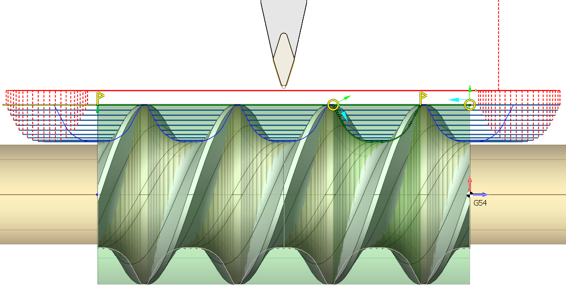
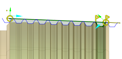
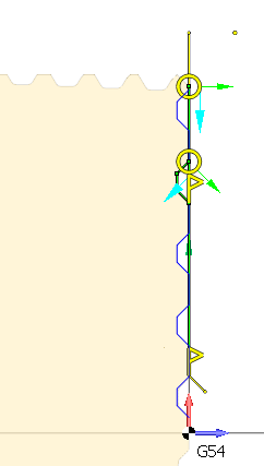
The profile threading operation allows you to make threads with a profile shape different from the tool's profile . This is achieved by removing material inside the entire thread groove with a series of consecutive passes, the mutual arrangement of which is calculated taking into account both the shape of the tool and the shape of the threaded groove itself. You must define two items in the Job Assignment: an item that determines the position of the beginning and end of the thread on the part and an item that defines the shape of the thread groove. Depending on the orientation of the given profiles, you can get a cylindrical, conical or face thread (archimedean spiral).


Job Assignment:
Threading. This option determines the location of the threaded section on the part. When you select this item, the system automatically generates the thread line on the part profile. You can interactively modify this line in the graphical window by moving the start and end points, changing the thread direction arrow, adjusting the threaded groove side arrow, and shifting the line to alter the external or internal diameter of the thread. Thread type - inner or outer - is specified by contour machining side (Perpendicular arrow near contour start point). Thread type - left or right - is specified by contour machining direction (Parallel arrow near contour start point) and spindle rotation direction. Contour approach and retract areas allows to set prolongation or chamfer for tool output. Each operation considers only one item from the Job Assignment. To process multiple threads, even with identical parameters, create as many operations as needed. This feature activates continuous cylindrical, taper or face threading mode (G23/G33) with constant step. In this mode synchronization between tool movement and spindle rotation is enabled. All tool movements will processed in thread mode until the interpolation switching or rapid toolpath command will be detected. If tool moves parallel to the spindle rotation axis, cylindric thread will be formed. If tool moves both parallel and perpendicular to spindle rotation axis simultaneously, taper thread will be formed. It is possible to form special face thread, if tool moves perpendicular to spindle rotation axis. In this case groove looks like spiral of Archimedes will be formed at face. G32/G33 command does not generate any moves, so all working tool moves, approaches, retracts, transitions to the next passes should be specified separate parameters in the Strategy and Links tabs .
Single thread cycle. This option also serves to define the position of the threaded section on the part. The system will output the G92 cycle to the NC program. It generates closed set of moves for one threading pass. Picture below shows processing schema. Before calling this cycle tool is in Start point. Cycle is called by one frame of NC-program, defines thread start point, step, taper size, chamfer size and others. As a result of this frame the tool goes from Start to TSP point, thread to TEP point and returns to Start point. Usually threading is processed by several passes, so NC-program consists several cycle calls with various thread diameters. Therefore, it can be used for both standard-shaped threads and free-form threads.

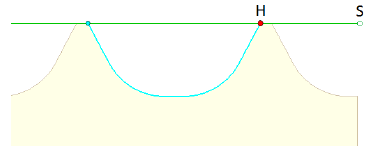
Threaded groove. This feature identifies the contour that determines the thread groove profile. The system will repeat this contour along the Threading or the Single pass thread at intervals equal to the Thread Pitch specified in the Cycle Parameters tab. You can interacively input the Thread Pitch in the graphical window. It is important to check that the groove's direction and side correspond to the Threading's or the Single pass thread's similar parameters. In the figure, the green curve marks the start (point S) and end points of the thread. The blue curve outlines the shape of the threaded groove. The point marked in red (point H) on this contour aligns vertically with the start of the thread at point S. Since the profile-defining curve can be anywhere relative to the start point of the thread, it is essential to correctly position point H.

Cycle Prarameters:
Cycle.
You can select one of the available turning cycles described in the Job Assignment. When you switch a cycle in this section, the corresponding element in the Job Assignment automatically changes. The set of parameters varies for each turning cycle.
Roll by arcs.
The system rounds the external corners of the toolpath by arcs with a radius equal to the tool nose radius. The parameters group works similarly to the OD Roughing and ID Roughing operations. See more.
Transformations:
Parameter's kit of operation, which allow to execute converting of coordinates for calculated within operation the trajectory of the tool. See more


