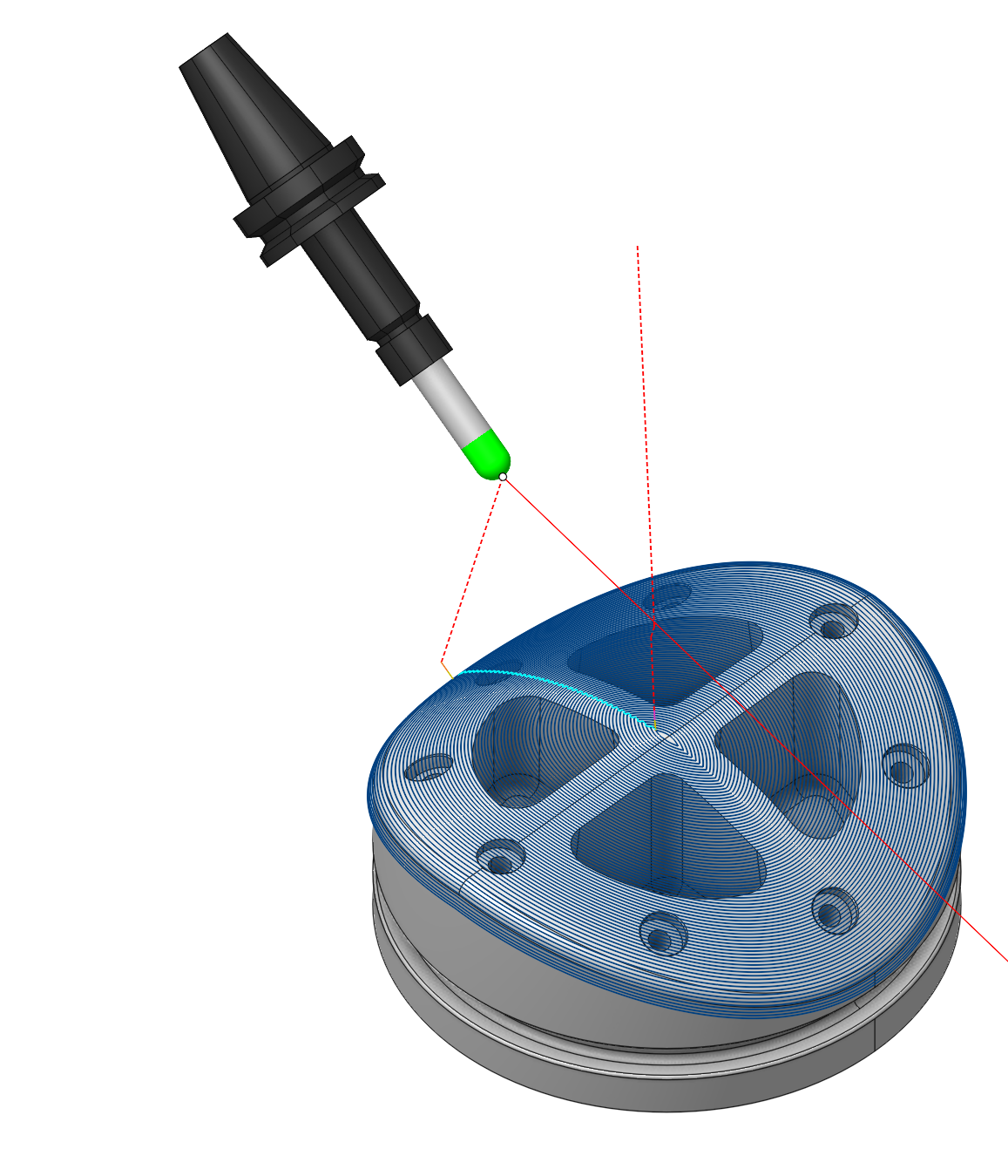
5D Surfacing operation
Application area:
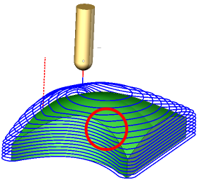
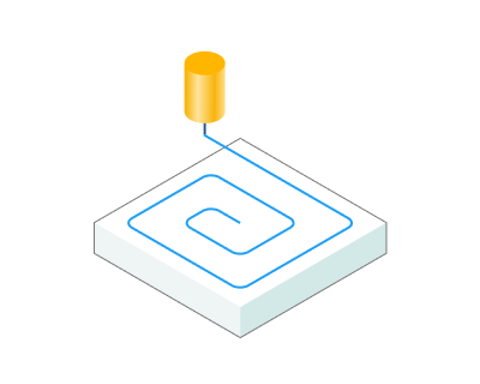
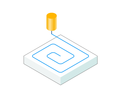
5D Surfacing operation is the operation from the finishing group and enables machining the surfaces of the model with a variety of strategies (parallel to planes, parallel to curve, morph, etc.) and tool axis orientation modes (fixed, normal to surfaces, to rotary axis, through point, through curve, etc.).
Job assigment:
Machining Surfaces. Select various surfaces of the part as the working task. The system will calculate the trajectory based on the chosen surfaces.
First Curve. For the Parallel to Curve strategy, this feature specifies curves for parallel passes computations. Additionally, in the Morphing Between Two Curves strategy, it specifies the First Curve . You can select one or multiple, not necessarily connected, curves or edges.
Second Curve. The system uses it in he Morphing Between Two Curves strategy. It specifies the Second Curve . You can select one or multiple, not necessarily connected, curves or edges.
Tilt Curve. This is t he curve that the tool axis vector aims at when setting Tool Orientation specification Through Curve.
Extended Geometry. Specify the surfaces tangentially to which you can extend the toolpath, and the lines across which you can elongate the toolpath.
First Surface. This feature s erves as the First Surface in a Morph Between Two Surfaces strategy, facilitating the morphing process to create toolpath lines.
Second Surface.
This feature s
erves as the Second Surface
in a Morph Between Two Surfaces strategy, facilitating the morphing process to create toolpath lines.
Surfaces for projection. These are the s urfaces intended for machining onto which the toolpath transfers when enabling the Project Toolpath onto the Part option in the Strategy tab.
Job Zone. Use the job zone to trim the passes outside the specified 2d containment areas. The plane of the containment area is defined by the initial tool orientation. See more.
Restrict Zone. In addition to Job Zones in system you can use Restrict Zones geometry from curves and edges to specify the workpiece areas that s hould avoid machining in the current operation. See more
Properties. Displays the properties of an element. It is possible to add the stock. You can also call this menu by double clicking on an item in the list.
Delete. Removes an item from the list.
Strategy:
Strategy:
This parameter allows the user to achieve a required toolpath:
Type of Strategy:
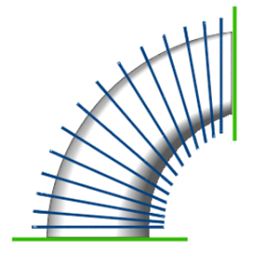
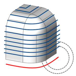
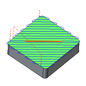
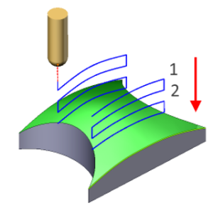
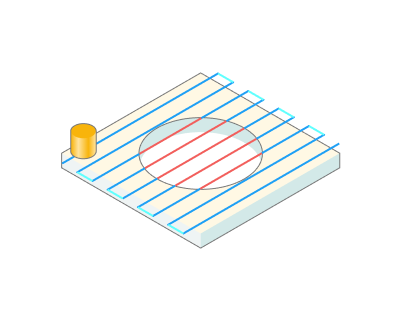
Parallel to Horizontal Plane. The system generates the tool passes as section lines of the Machining Surface by horizontal planes (planes are perpendicular to the tool axis), similar to the strategy in a Finishing Waterline operation. See more.
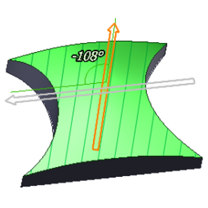
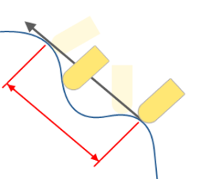
Parallel to Vertical Plane. The system generates the tool passes as section lines of the Machining Surface by vertical planes (planes are parallel to the tool axis), similar to the strategy in a Finishing Plane operation. You can change the angle of the plane around the tool axis. See more.
Parallel to 3d Plane. The system generates the tool p asses as section lines of the Machining Surface by planes positioned at adjustable angles in space.
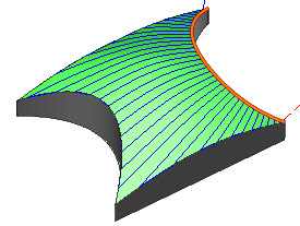
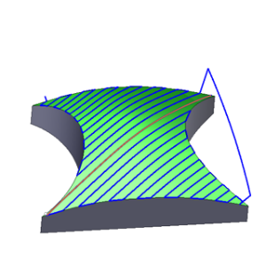
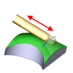
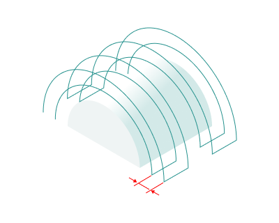
Parallel to Curve. The system generates the tool p asses on Machining Surface at a specified Step parallel to the First Curve defined in the Job Assignment.
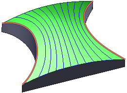
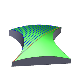
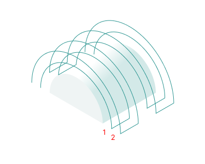
Morph Between Two Curves. The system generates the tool p asses as geometric points arrays on the Machining Surface, maintaining a constant ratio between the distance from the point to the First Curve and the distance to the Second Curve for each pass.
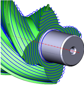
Around Rotary Axis. The system generates the tool p asses as sections of the Machining Surface at a specified Step by employing cylinders with an axis specified as the Rotary Axis.
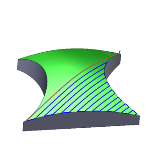
Across Curve. The system generates the tool p asses as section lines of the Machining Surface with planes perpendicular to the First Curve specified in the Job Assignment.
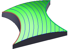
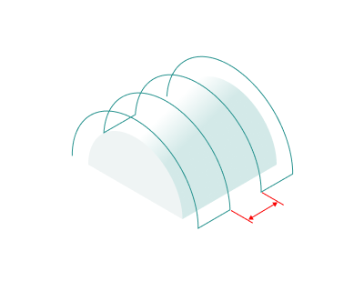
Morph Between two surfaces. The system generates the tool p asses as section lines of the Machining Surface by surfaces formed through a smooth transition from the First Surface to the Second Surface, at intervals according to the Step.
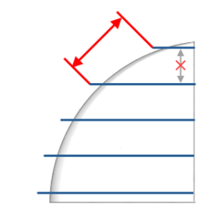
Step. The maximum allowed width of cut . See more.
Adaptive Step. This parameter adjusts the distances between tool passes according to the curvature radii of the surface and the tool to maintain uniform scallop height after surface machining. See more.
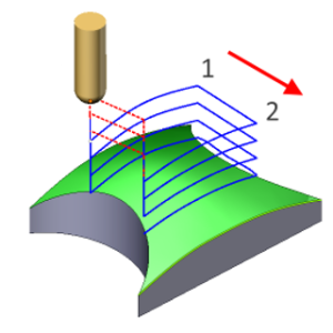
Calculate Based on Tool Center. Flagging switches the mode that involves first offsetting the surfaces for machining by the tool profile for 3-axis machining or along the surface normal by the tool radius for 5-axis machining, and then calculating toolpath curves on these offset surfaces. In another mode, the system initially generates tool path as curves on the machined surfaces. Then, it positions and orient the tool relative to the calculated curves to keep the tool's contact point with the machined surface constant.
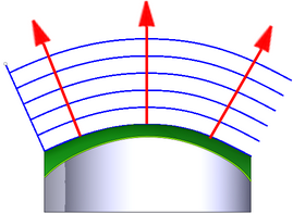
Comparison of the toolpath based on the center and the tool contact point:
Calculation based on tool contact point:
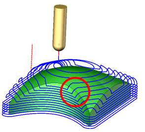
In this mode the work passes are generated by calculating curves on the machining surfaces as the first step and then positioning and orienting the tool relative to the calculated curves in such a way that the point of contact of the tool with a machining surface stays the same. It is desirable, for example, when smooth surfaces are machining, or doing flank milling.
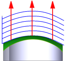
Calculation based on tool center:
In this mode the work passes are generated in such a way that at first the machining surfaces are being offset either by the tool shape itself for 3 axis machining or by the tool radius along the surface normal for 5 axis machining and only then the sections of the offset surfaces are calculated. For example, for the Parallel to plane strategies it means that the generated work passes all lie on parallel planes. Another advantage of this mode is that not only the surfaces themselves but the edges between machining surfaces are taken into account.
XY Angle. This is the r otation angle of the section planes around the tool axis. See more.
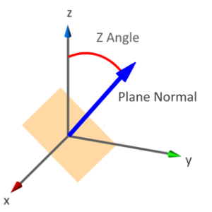
Z Angle. This is the a ngle between the Z-axis and the normal to the section plane.
Use 2d Curves. When flagging, the system generates the toolpaths relative to curves projected onto the XY plane in Parallel to Curve and Morphing between Two Curves strategies.
One Side Machining. In the Parallel to Curve and Morph between Two Curves strategies, it controls the placement of the toolpath relative to the curves specified in the Job Assignment. Without the flag, the system generates toolpath on both sides of the curve.
Left. The system generates passes on the left side of the curve specified in the Job Assignment.
Right. The system generates passes on the right side of the curve specified in the Job Assignment.
Extend Curves to Infinity. Setting the flag allows the system to extend the passes parallel to the selected lines up to the edges of the Machining Surface when the curves are smaller than the Machining Surface.
Rotary Axis. This is t he axis of section cylinders in the Around Rotation Axis strategy.
Milling Type:
Сan be assigned in almost all operations, except for the curve machining operations. This allows the user to control the required milling type (climb or conventional) during the toolpath calculation process. See more
The parameters of the Milling Type are the same. as in the Waterline Roughing operation. See more.
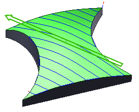
Sorting:
Controls the sequence of toolpath passes during surface machining.
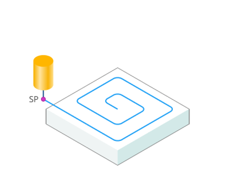
Start Point. Activating the flag permits the input of coordinates marking the starting point of working passes in surface machining.
Machining Order. Controls the execution order of the tool's working passes. See more
Downwards. Working passes proceed from top to bottom, from the nearest pass to the furthes.
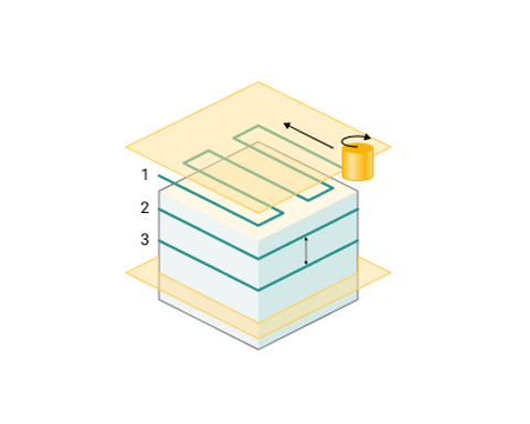
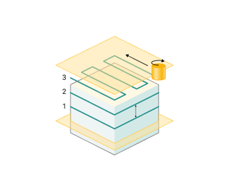
Upwards . Working passes proceed from bottom to top, from the most distant pass to the closest one.
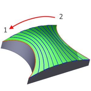
From First to Second . Operation executes passes from the First towards the Second Curve or Surface.
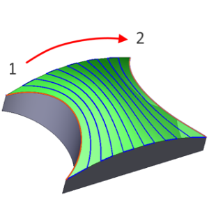
From Second to First . Operation executes passes from the Second towards the First Curve or Surface.
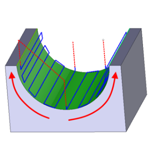
From Outside in . Working passes proceed from the periphery towards the midpoint of the Machining Surface.

From Inside Out . Working passes proceed from the midpoint towards the periphery of the Machining Surface.
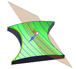
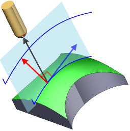
Tool Orientation:
Controls tool axis orientation.
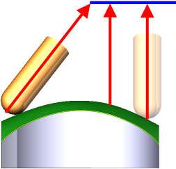
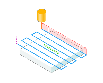
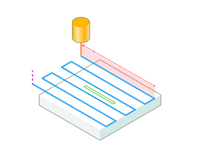
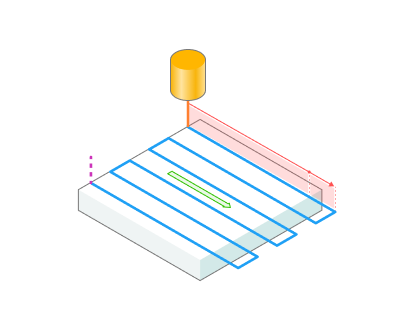
Fixed. Throughout the toolpath, the tool maintains a fixed orientation, defined by the initial positions of the machine's rotary axes as configured in the Setup tab.
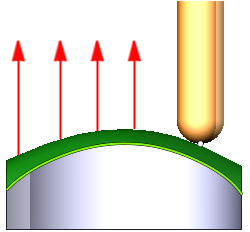
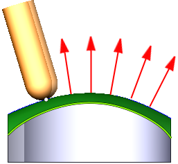
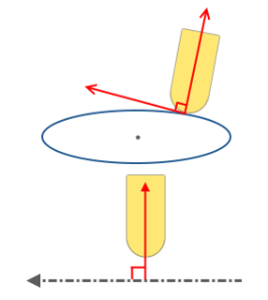
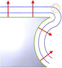
Normal to Surface. T he system orients t he tool axis normal to the Machining Surface.
Flank . The tool's side part machines the surfaces.
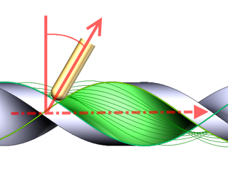
To Rotary Axis. The system directs tool's axis vector from the designated Rotary Axis.
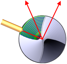
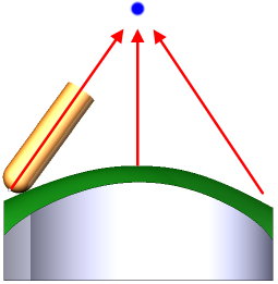
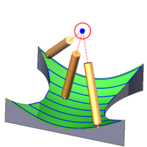
Through Point. The system directs tool's axis vector towards the designated point (pole).
Through Curve. The tool axis vector targets the nearest point on the Tilt Curve specified in the Job Assignment.
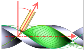
Perpendiculat to Toolpath. The tool's axis stands perpendicular to the tangent of the trajectory while being parallel to the Rotary Axis.
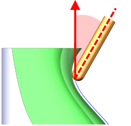
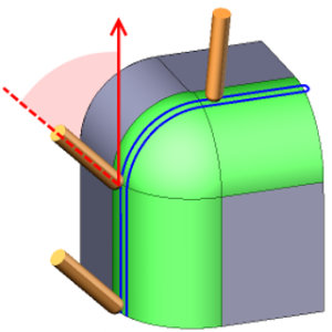
Vertical Clearance Angle. When the flag is set, the system automatically tilts the tool to the specified angle at areas where the Machining Surface displays a steep or negative incline (with the surface normal pointing down relative to the tool's axis), making it possible to machine simple areas with undercuts.
Rotary Axis. Setting the flag locks one of the components of the tool orientation vector, maintaining a constant Side Angle between the tool axis and the perpendicular to the specified axis (or the axis itself if the Tool Orientation is set as Perpendicular to Toolpath) .
Side Angle. Specifies the inclination angle value of the tool axis relative to the axis designated as the Rotary Axis.
End Side Angle.
Specifies the inclination angle value of the tool axis relative to the axis designated as the Rotary Axis at the end of the toolpath.
Inverse Tool Axis Direction. Alters the tool axis vector direction. Use this parameter if CAM system incorrectly attempts to machine surfaces from the opposite side to the desired one or if it fails to generate a toolpath..
Lead Angle. It is a n additional tool tilt angle within the plane of motion direction.
End Lead Angle.
It is a
n additional tool tilt angle within the plane of motion direction at the end of the toolpath.
Lean Angle. It is a n additional tool tilt angle within the plane ortogonal to the motion direction.
End Lean Angle.
It is a
n additional tool tilt angle within the plane ortogonal to the motion directionat the end of the toolpath.
Inverse Lead Angle. When flagging, t he lead angle sign becomes the opposite when the direction of tool movement changes.
Normal Blend Distance. The distance along the toolpath where the tool's tilt angle remains constant.
Axial Displacement. The feature shifts the contact point of the tool and the Machining Surface along the tool's axis.
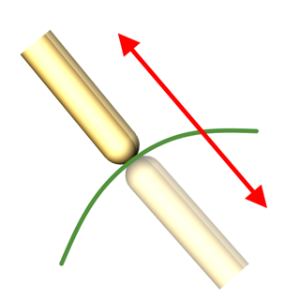
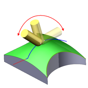
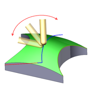
Lean Angle 1. If the Tool Orientation is set as To Rotary Axis it is the angle by which the tool deviates in the positive direction from the initial vector in a plane perpendicular to the Rotary Axis.
Lean Angle 2. If the Tool Orientation is set as To Rotary Axis it is the angle by which the tool deviates in the negative direction from the initial vector in a plane perpendicular to the Rotary Axis.
Origin . Specifies the pole coordinates if the Tool Orientation is set as Through Point.
Limit Rotation Angles:
When the flag is set, it specifies the limit values of the tool's angular position relative to the specified axis.
Around X (YZ). Activating the flag defines the tool's tilt limit values relative to the X axis within the YZ plane.
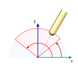
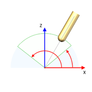
Around Y (XZ). Activating the flag defines the tool's tilt limit values relative to the Y axis within the XZ plane.
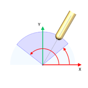
Around Z (XY). Activating the flag defines the tool's tilt limit values relative to the Z axis within the XY plane.
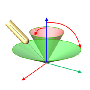
Conical limit. Activating the flag establishes maximum and minimum tilt angles of the tool relative to the designated axis, constrained by two cones with specified angles.
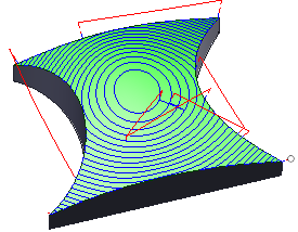
Job zone.
Enables additional modification of the working area initially selected on the Job assignment tab.
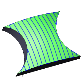
Margins. For strategies that run parallel to planes, there are constraints on the positioning of slicing planes.
Full. There are no constraints on the formation of slicing planes.
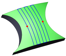
Points. Arrange slicing planes between two designated red points. Use the mouse to drag these points to the appropriate locations in the graphic window.
Start Margin. I n curve or surface-based strategies, the parameter determines the offset from the First Curve or Surface , i where the toolpath formation begins.
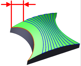
Zone Width. In curve or surface-based strategies, the parameter determines the distance from the Start Margin to t he last machining pass.
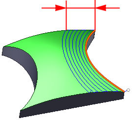
End Margin. The parameter defines the offset from the Second Curve or Surface , up to which the toolpath is formed.
Limit Job Zone . In the Across Curve strategy, it allows using for the trajectory only the section of the Machined Surface closer to the current point on the curve.
Some parameter group works similarly to the Plane finishing operation. See more
Corners smoothing.
When there is a sudden change of the tool direction, the milling control performs deceleration before starting the turn, and then accelerates again. This fact can lead to vibrations and high tool and milling machine wear. The problem can be solved if the toolpath has very few or no breaks. For this reason, in the system there is the toolpath smoothing function using the defined radius for machining inner or outer corners of the model.
Blend Distance. Smoothing occurs within this distance inside the sharp corner.

Roughing Passes.
Toolpath is offset in plane by the Roughing passes thickness amount. Additional passes are added to the contour by the value specified in the parameters with the specified number of steps.
Orientation of roughing passes:
By Surface Normal. Calculating roughing paths involves offsetting the finish paths along the surface normal direction.
Along Tool Axis. Calculating roughing paths involves offsetting the finish paths along the tool's axis.
In Tool Plane. Calculating roughing paths involves offsetting the finish paths within the plane of tool motion . This approach is effective for the strategy Parallel to Vertical Plane and when surfaces are machined with the end part of the tool.
Perpendicular to Tool Axis. Calculating roughing paths involves offsetting the finish paths within the plane perpendicular to the tool axis, . This approach is effective for the strategy Parallel to Horizontal Plane.
By Default. Displays the default calculation method adopted in the system.
Count. It is the count of rough passes.
Step. It is the distance between rough passes.
Sort By. Specifies the execution order for rough passes.
Levels. Rough passes are executed in the order of the layers' arrangement.
Strings . Rough passes are executed in the order of the strings' arrangement.
Project Toolpath onto the Part:
By setting the flag, the system generates tool paths for processing the surfaces identified as Surfaces for Projection in the Job Assignment by mapping the path derived from the Machining Surface onto the Surfaces for Projection.

In this instance , identify auxiliary geometry surfaces, obtainable through extra constructions in the CAD module, as the Machining Surfaces instead of the part surfaces needing direct milling. Arrange these surfaces so that projecting the toolpath from them is straightforward. Declare the milling surfaces as the Surfaces for Projection.
Trimming:
Allows for the skipping of surfaces
not intended for machining
and allows for the extension of the toolpath.
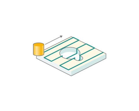
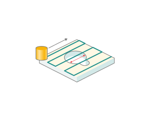
Hole Capping. Activating this option allows the system to skip holes with diameters that are equal to or smaller than the specified dimension. See more
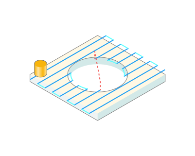
Gap capping. By enabling this feature, the system can close toolpath gaps smaller than the specified dimension.
Extend (+)/Trim (-) passes. With this setting, users can extend or trim the initial and final segments of the toolpath.
Start. Entering a positive value, the system extends the start of the working passes of the toolpath by the specified amount. Entering a negative value shortens the beginning of the passes.
End. Entering a positive value, the system extends the end of the working passes of the toolpath by the specified amount. Entering a negative value shortens the end of the passes.
Transformations:
Parameter's kit of operation, which allow to execute converting of coordinates for calculated within operation the trajectory of the tool. See more.